1. Types of Drawings and Prints
1.1 Introduction
Learning Objectives
- Explain the difference between drawings and prints
- Describe engineering drawings
Terms
- Design phase
- Production phase
- Computer-aided drafting (CAD)
- Three-dimensional (3D) model
- 3D printers
- Computer Numerical Control (CNC) machines
- Detail drawings
- Print reading
Have you ever considered the steps that go into making the everyday products on which we rely? In manufacturing any part, a drawing is crucial; this can vary from simple objects like a paper clip, which might need just a handful of drawings, to complex products such as computers or cars that require thousands of drawings for their creation.
The details of a person’s design are communicated through the use of drawings and prints. This chapter will introduce the manufacturing process and the use of drawings and prints within the manufacturing process.
1.2 The Manufacturing Process
The process of manufacturing a part or component can be condensed into two categories. The first process is the design phase, where a person’s or a group’s ideas are moved to drawings and prints. The second process is the production phase, during which these drawings and prints are used to produce the final product.
1.3 Design Phase
After identifying the need or intent to develop a product, a specialized design team is assembled. This team typically comprises designers and engineers responsible for generating the essential documentation to achieve the design objectives. Additionally, machinists and inspectors are included to ensure that the design can be produced efficiently. This critical stage, the design phase, involves creating all necessary documents required for product fabrication.
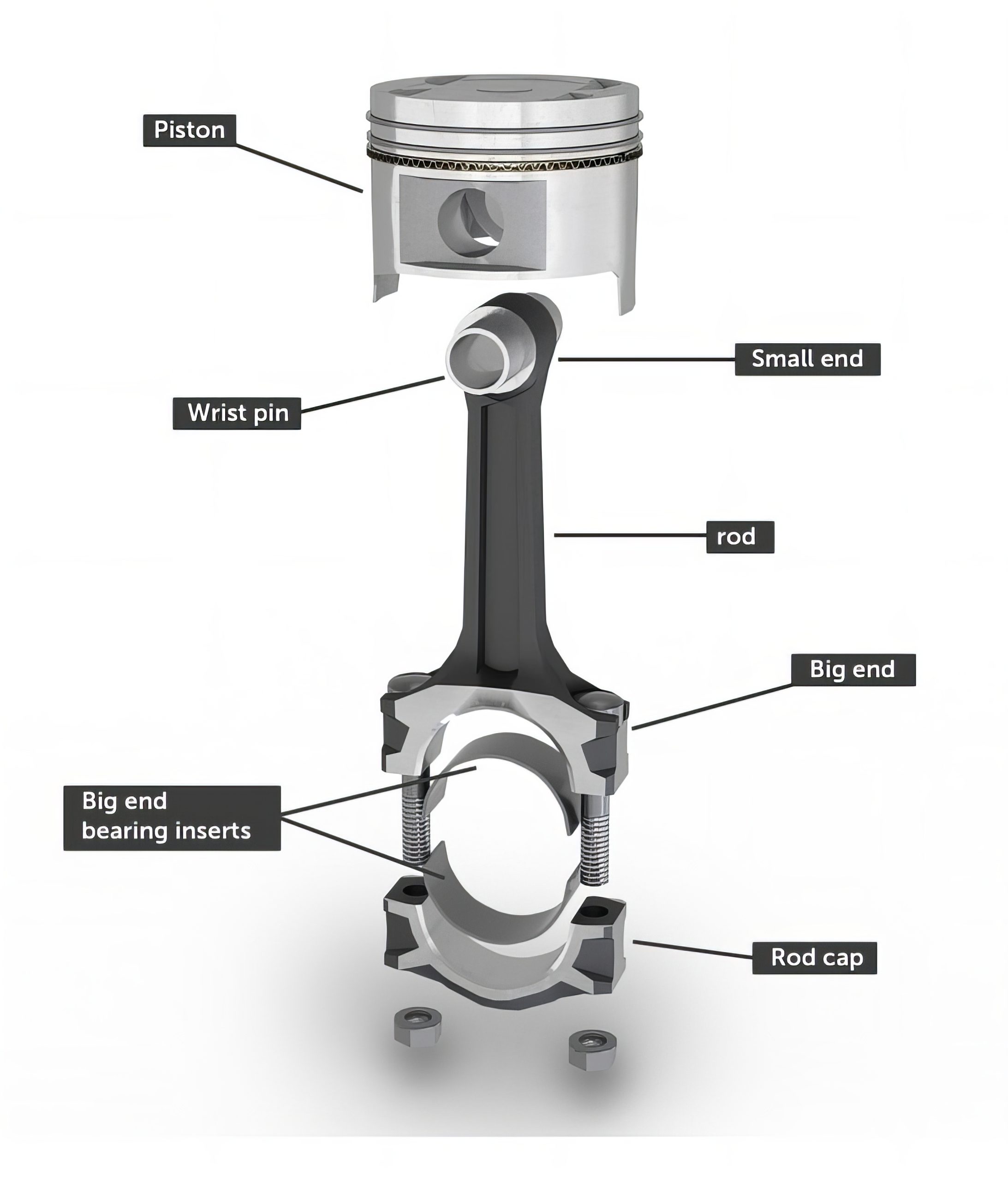
Most products consist of multiple components. For example, see Figure 1-1. Each of these components is separately designed and frequently manufactured in different locations, often by distinct companies both domestically and internationally. These components are then transported to a specified location for assembly.
1.4 Three-Dimensional Models
Individual components are typically designed through computer-aided drafting (CAD). A CAD system is a software program created to increase the speed, efficiency, accuracy, and modification of designs. CAD systems also allow the design to be created three-dimensionally. Before CAD systems were created, every design had to be drawn by hand.
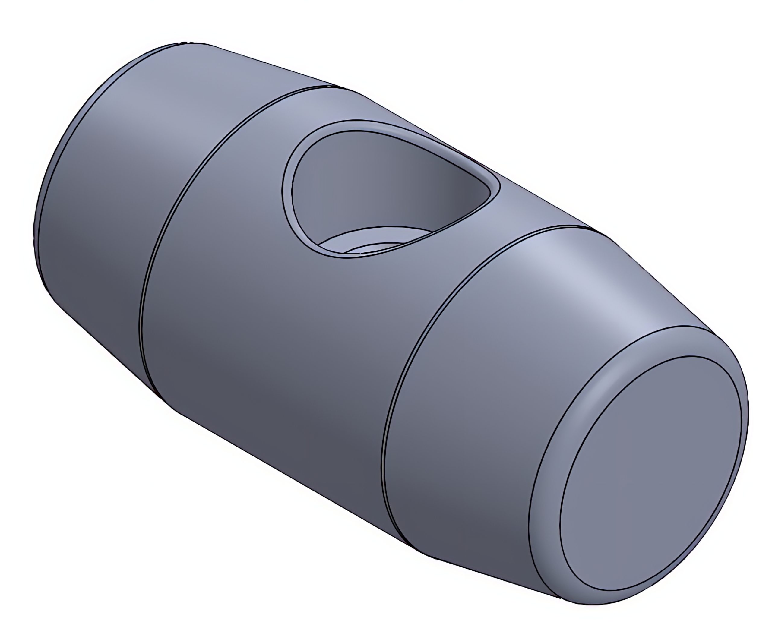
A three-dimensional (3D) model is a digital representation of an object that allows the part to be viewed from multiple perspectives (see Figure 1-2). Having a 3D model of the design offers several advantages in creating and analyzing the design.
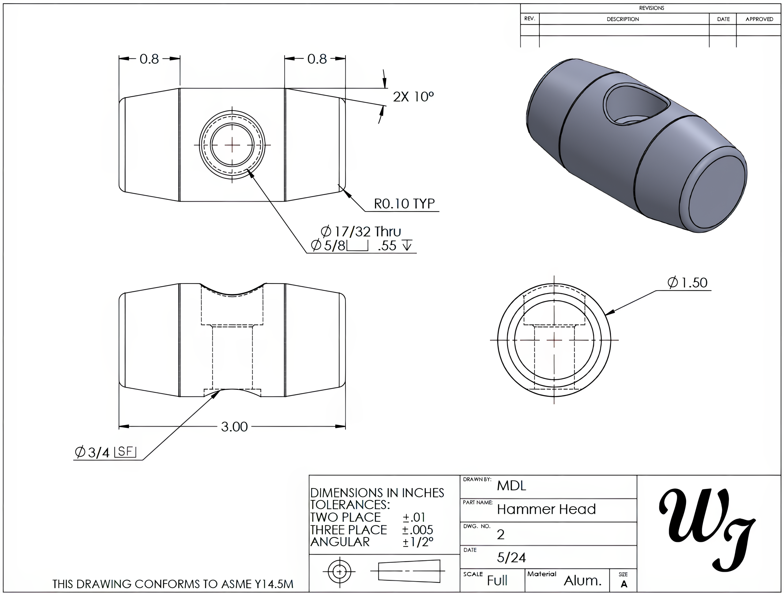
A CAD system can quickly generate a detailed multi-view drawing from a 3D model, automatically transferring the model’s details and dimensions to a two-dimensional (2D) drawing. See Figure 1-3. Any changes made to the 3D model can be automatically updated on the 2D drawing file.
- Analyzing and Simulating. A 3D model may be used with different software to create a calculated simulation of how the part or assembly will perform. Examples include simulating the manufacturing process or stress-testing a product when it is in service. These simulations allow for design adjustments prior to the production of parts, which saves time and material costs. Some examples would be a part’s material may be used to predict how the part will react to stresses, or a 3D model of a part’s mold can be used to simulate how the material will flow into the mold. Allowing design adjustments to be made before the parts are produced also saves time and material costs.
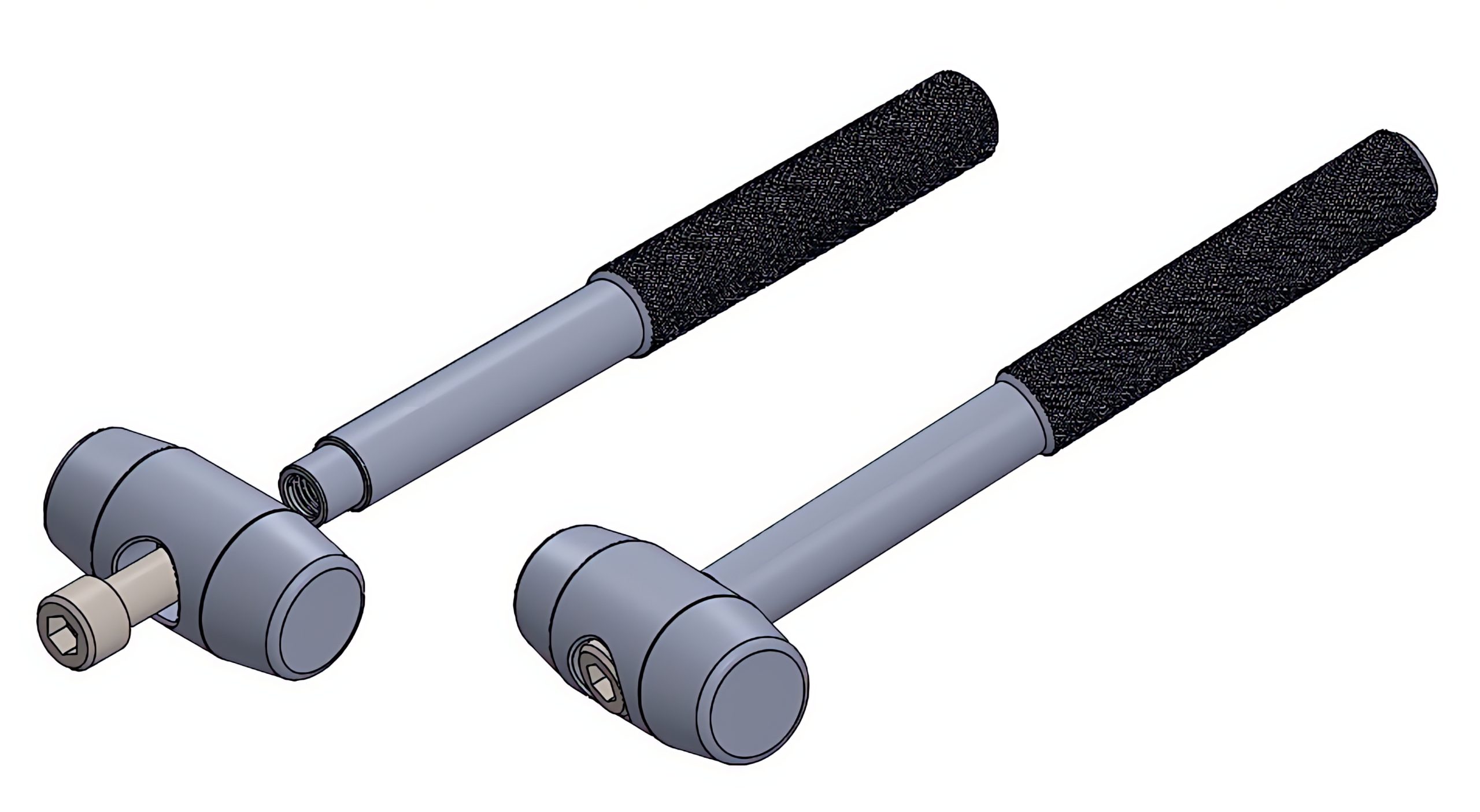
- Verifying Assembly of Components. A 3D assembly may be created from the individual component models to represent the final assembly, as shown in Figure 1-4. This can be used to verify how the final assembly will perform before an actual part is produced. This assembly can then be used to create 2D drawings of the final assembly.
- Transferring the Model Directly to Production. A 3D model can be used in software to create programs to be used by 3D printers or by Computer Numerical Control (CNC) machines to produce a physical part. 3D printing, also referred to as additive manufacturing, is the building up of a three-dimensional object from a digital 3D model. This can be done in various processes where material (often plastic or a powdered metal) is deposited or joined together, typically layer by layer. A CNC machine is a computer-controlled device used to automate the operation of machine tools like lathes, mills, grinders, and routers. These machines follow programmed instructions to execute precise machining tasks, shaping materials such as metal, plastic, wood, and composites into desired forms.
1.5 Drawings
The creation of detail and assembly drawings represents a crucial stage in the design process. Detail drawings are two-dimensional drawings that provide comprehensive information necessary to manufacture each part. These drawings not only provide dimensions that outline the shape and size of the part but also detail other important features. Additionally, drawings convey essential specifications such as material types, allowable size variations, and feature placements, ensuring all aspects are communicated clearly for production.
To help ensure part specifications are accurately conveyed through detailed drawings, companies adhere to drawing and manufacturing standards. These norms have been thoughtfully established by respected organizations such as the American Society of Mechanical Engineers (ASME), the American National Standards Institute (ANSI), and the International Organization for Standardization (ISO).
It is imperative to have a comprehensive understanding of detail drawings to effectively interpret assembly drawings. Assembly drawings identify each component within a product and illustrate the manner in which these parts interconnect. Both detail and assembly drawings are created from the 3D models in CAD software.
1.6 Prints
The term “print” is often used to describe a physical copy of a part drawing, although in many industry settings, the words “print” and “drawing” are frequently used interchangeably. Understanding or interpreting the information presented in these drawings is known as print reading. Most physical paper prints are larger than a standard 8.5” x 11” sheet of paper and must be created using a plotter. However, many companies today are choosing to skip paper prints altogether, having them viewed by the reader electronically on larger computer screens, tablets, or laptops. This can save time not having to move paper copies through several departments or large production floors, as well as ensuring that the latest version of the print is being used by the reader. However the drawing is being viewed, print reading is an essential skill for anyone in the manufacturing field.
1.7 Blueprint
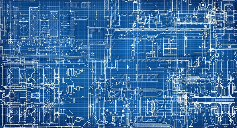
The term “blueprint” has its roots in a time when these prints featured a blue background with white lines and symbols. Old blueprints were created by first sketching the design on tracing paper and inking the lines, as shown in Figure 1-5. The inked tracing paper was then placed on light-sensitive paper and exposed to ultraviolet light. This caused a chemical reaction, turning the exposed areas blue. This process required skilled draftsmen, resulting in the characteristic white lines on a blue background in blueprints.
Even today, many people continue to use the word “blueprint” when talking about drawings. These types of drawings were phased out when the printer, plotters, and copy machines became popular.
Learning Activities
Exercise 1
References:
Barsamian, M. A., & Gizelbach, R. A. (2015). Unit 1 drawings and prints. In Machine trades print reading (7th ed.). Goodheart-Willcox.
Lorier, M. (2024). Simplified AI. [Large language model]. https://simplified.com/ai-writer
Images:
All images by Mark Lorier and licensed under CC BY-NC 4.0 except where otherwise noted.
Figure 1.1: “Drawing_of_a_connecting_rod_in_an_automobile_engine” by Abouttools is licensed under CC BY-SA 4.0

