9. Print Symbols and Notes
9.1 Introduction
Learning Objectives
- Interpret notes commonly found on prints
- Identify symbols found on prints
- Interpret surface texture symbols found on prints
- Interpret machining symbols found on prints
- Interpret common geometric symbols found on prints
Terms
- General note
- Local note
- Fillet
- Round
- Counterbore
- Spotface
- Countersink
- Chamfering
- Depth symbol
- Surface texture
- Surface roughness
- Surface texture symbol
- Waviness
- Lay
- Surface finish comparator
- Profilometer
- Datum
- Basic dimension
Surface finish symbols offer essential insights into the desired texture and quality of a component’s surface. They outline key parameters like roughness, waviness, and lay patterns—guiding manufacturers toward achieving the ideal finish that balances functionality and aesthetics.
Geometric symbols are equally important in print reading. They clarify how parts should be shaped, oriented, or positioned relative to one another. These symbols outline critical dimensions pertaining to angles, radii, concentricity, and symmetry, among other features.
Prints often contain notes that provide supplementary information or instructions in addition to symbols. These notes may include material specifications, manufacturing processes, assembly instructions, safety warnings, or any other relevant details crucial for successfully interpreting the design.
9.2 Drawing Notes
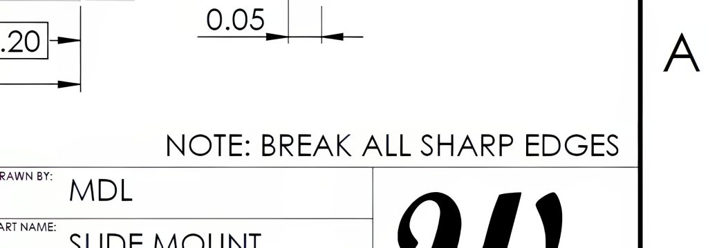
In reviewing drawings, you might come across various notes that serve essential purposes. These notes will fall into one of two categories: a general note or a local note. General notes relate to the entire print, typically positioned above or near the title block. These may include vital details like tolerances, finishes, or material specifications as shown in Figure 9-1.
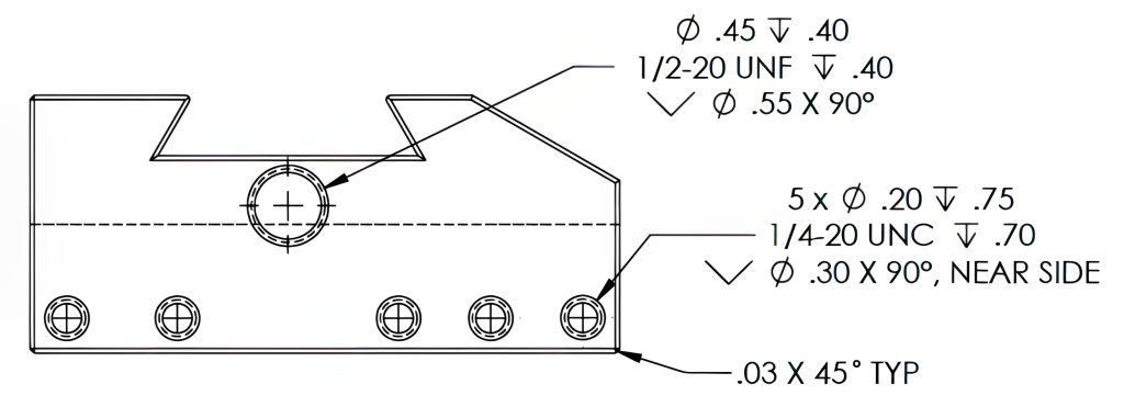
Local notes are more specific notes that address only particular drawing features. These local notes will typically use leaders to point directly to where they apply—for instance, providing information about hole sizes, a chamfer, radius, or special features, as depicted in Figure 9-2. Paying attention to both types of notes is essential as they contribute significantly to understanding the drawing’s intent and requirements.
9.3 Dimensioning Symbols
As the use of prints becomes increasingly global, there’s been a meaningful shift toward international standardization in drawings. This change often favors symbols over words and abbreviations for clarity and understanding. Below are some standard symbols commonly utilized in dimensioning systems with which you should become familiar.
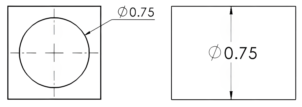
The diameter symbol identifies a circular feature. See Figure 9-3. A diameter symbol is used with a value to apply to the circle’s diameter size. Previous drawing standards have used the abbreviation for diameter, “DIA.” Although this DIA abbreviation is no longer a current standard, this may still be observed in drawings.
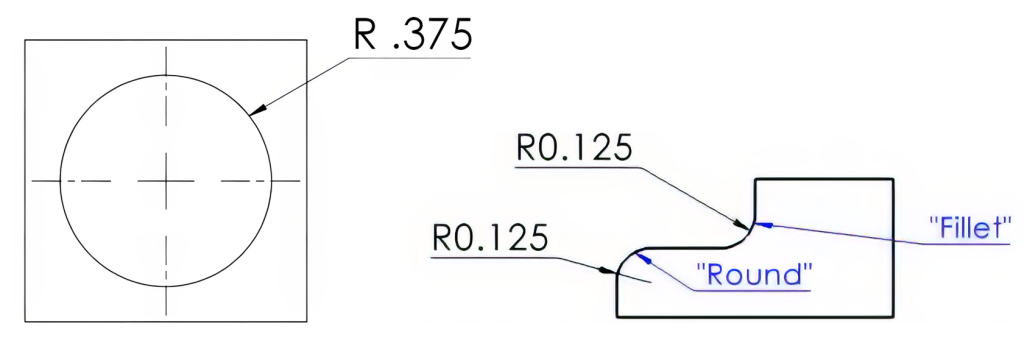
The “R” for radius or radii is used to identify a partial or complete circular feature. The “R” may be used instead of diameter when a circle is dimensioned from the center. A radius value is also used in partial circular features or when removing sharp edges of surface intersections. Radius values are also applied at intersections of surfaces to avoid sharp edges or corners. The internal radii are called fillets; external radii may be called rounds, as shown in Figure 9-4.
The square symbol may be used to indicate a square feature with four equal sides and equal 90° angles. It may also eliminate the need for additional dimensioning. In Figure 9-5 this symbol identifies the features as square and eliminates the need to provide dimensions for the two sides because the sides of a square will be equal.

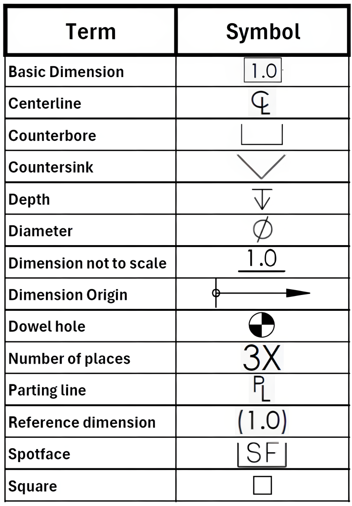
This squared “U” shaped symbol is used for a counterbore. A counterbore enlarges a hole at one end. A counterbore is commonly used to allow the head of a fastener to sit flush or below the surface. The abbreviations of “C’BORE” or “CBORE” for counterbore have been used in previous drawing standards and may still be observed on drawings. In Figure 9-6, the counterbore symbol is used to identify the features as being counterbores. In the Figure 9-6 examples, the first counterbore symbol is followed by the diameter and depth of the counterbore, and the second example only has the counterbore diameter following the symbol with the depth identified in the other view.

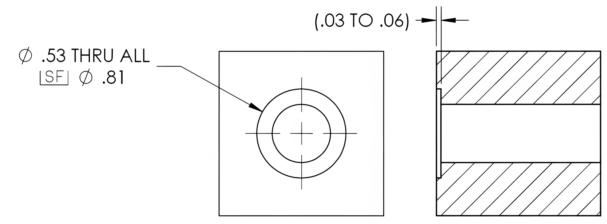
With the addition of “SF,” the counterbore symbol will indicate that a spotface operation is required. A spotface is an operation used to provide a smooth, flat, circular surface for a mating part or a fastener to contact the material around a hole. A spotface is often found on material that may not already be flat, such as a cast or molded part, where a fastener is placed near a fillet or raised surface, causing an interference. The depth of a spotface is typically .03 to .06 of an inch unless a specific depth of the spotface is noted or dimensioned. Previous drawing standards used the abbreviation “SFACE,” which may still be found on drawings instead of the symbol. The example in Figure 9-7 uses the spotface symbol to describe the feature and the depth of the feature.
Represented by a wide “V”-shaped symbol, a countersink is a cone-shaped recess created in the material at the end of a hole. Countersunk holes allow a flathead fastener to sit flush or below the surface. The abbreviation of “CSK” had been used in previous drawing standards and may still be seen on drawings. This countersink symbol is also used for chamfering or removing the sharp edges of the hole. The angle included for the countersunk holes will follow the symbol. These included angles are often either an 82° or a 90° angle. The included angle of a metric flathead fastener is 90°, while an inch flathead fastener will have an 82° angle. In the example of Figure 9-8, the countersink symbol is used to identify the feature shape with the size of the outside diameter of the countersink and the angle following the symbol.

The depth symbol, followed by a numerical value, is used in drawings to communicate the required depth for features such as holes, slots, or recesses. The symbol features an arrow pointing down with a horizontal line on the top. Previous drawing standards used the abbreviation “DP” in place of the depth symbol; this abbreviation may still be found in some drawings. Figure 9-9 features depth symbols followed by the depth value.

Figure 9-10 below shows a list of these symbols and other symbols used in the ANSI and ISO engineering drawing standards.
9.4 Surface Texture
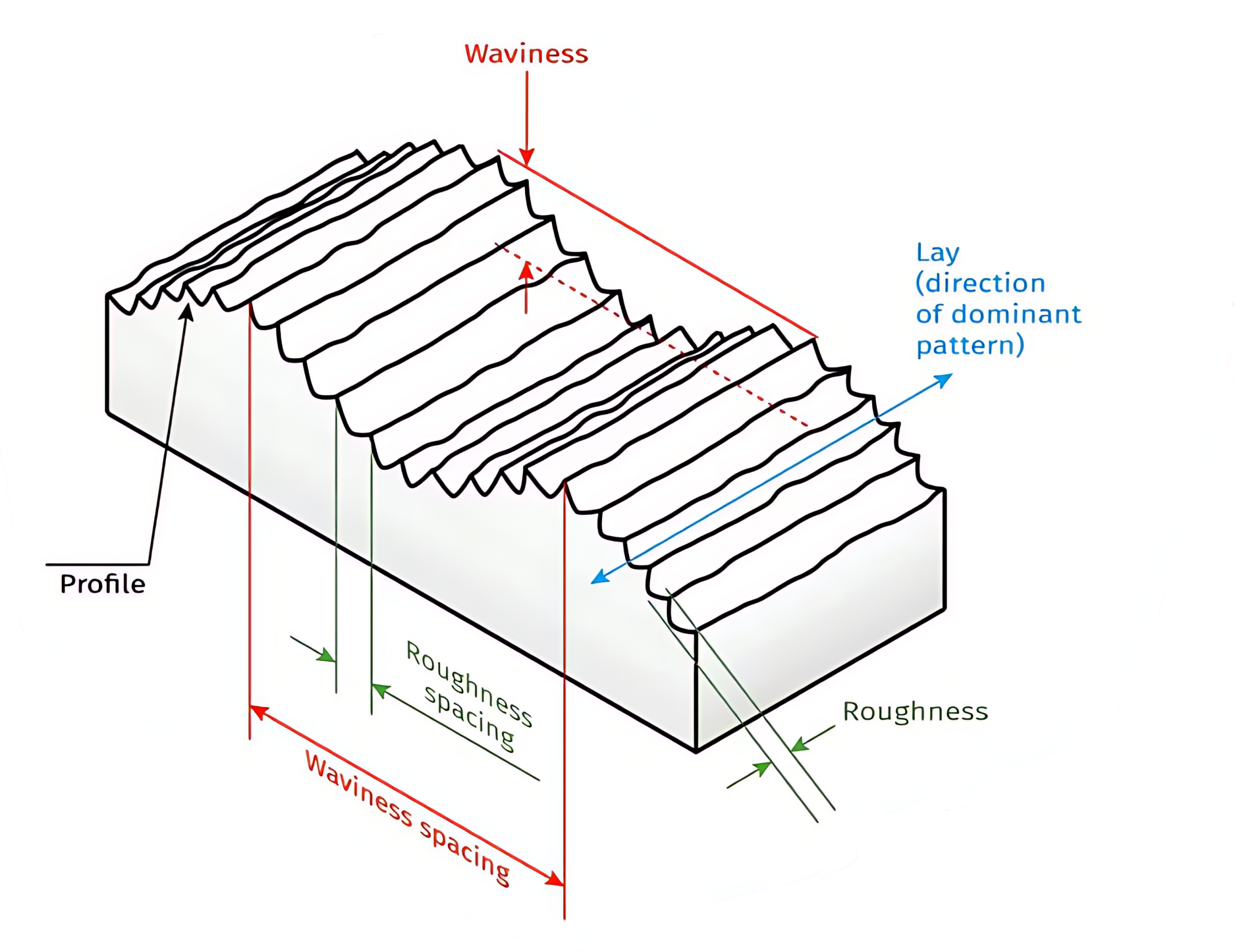
Surface texture refers to the comprehensive quality of a surface and is defined by its waviness, lay, and roughness characteristics. When collectively considering all aspects of waviness, lay, and roughness, the term “surface texture” is frequently used to prevent misunderstandings because machinists commonly use “surface finish” to denote surface roughness. Figure 9-11 illustrates waviness, lay, and roughness as they are applied to a part’s surface.
Surface Roughness
Surface roughness refers to small irregularities in the surface geometry. It is often referred to as “surface finish” because it is the most commonly specified aspect of surface texture. This roughness value is measured as an average reading in microinches (millionths of an inch) or micrometers (millionths of a meter), meaning a reading of 63 would represent an actual value of .000063 inches, and a value of 1.6 would represent an actual value of .0000016 meters.
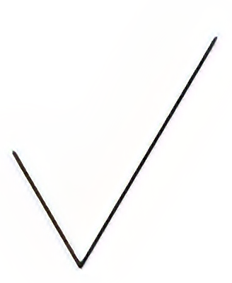
The basic surface texture symbol is a checkmark with the bottom point resting on the surface to be specified and the value above the point. Figure 9-12 displays basic surface finish symbols used to identify the required surface finish to apply to the features and surfaces of a part. A general note may be used to identify the finish of the entire part with the abbreviation “FAO” for Finish All Over.
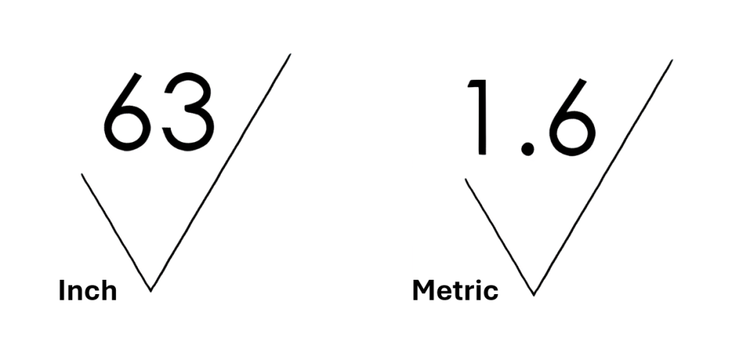
With this open checkmark symbol, the designer does not specify the methods required to produce the desired surface finish. See the basic surface texture symbol in Figure 9-13.
Material Removal by Machining is Required
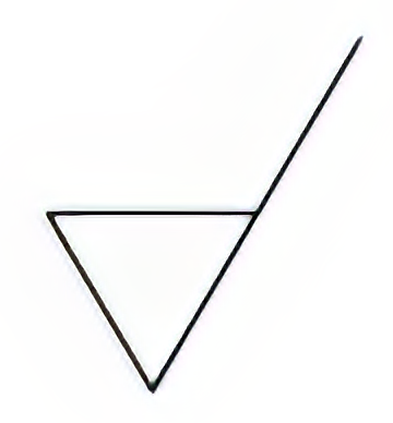
When a horizontal bar is added to the symbol, it indicates that the surface is to be machined to produce the finish required, as shown in Figure 9-14.
Material Removal Prohibited
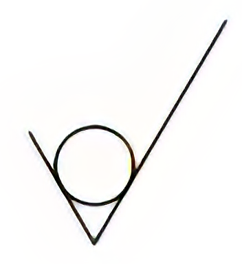
With a circle placed in the check symbol, the required finish must be obtained without removing material. The finish must be produced by processes such as casting, die casting, or injection molding. View Figure 9-15.
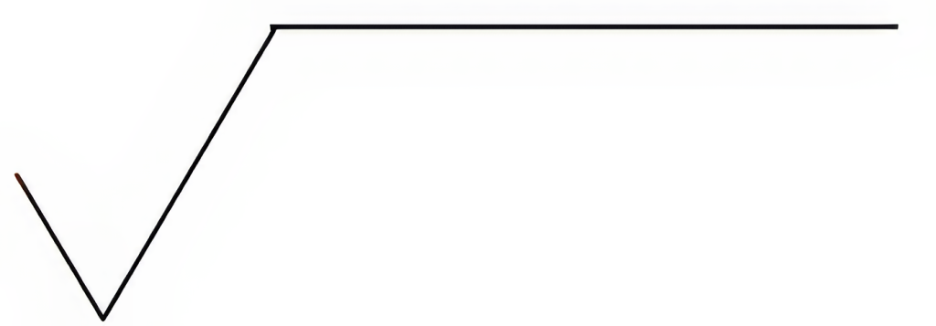
To add additional information, including sampling length, waviness, and direction of the surface lay, a horizontal line is added to the check mark symbol. View Figure 9-16.
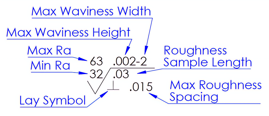
As with many of the standard practices provided by the ANSI and ISO drawing standards, the surface texture rules have also evolved. Figure 9-17 illustrates a surface texture symbol with commonly used placement of surface texture information, although some variation may be observed between drawing standards. This example provides placement for maximum roughness average (Max Ra) and minimum roughness average (Min Ra), maximum waviness height and width, roughness sampling length and spacing, and lay symbol.
Waviness
Waviness refers to the irregularities or deviations from a desired smooth surface that occur over a longer distance than roughness. It represents the larger-scale variations in the surface texture.
Waviness is typically characterized by longer wavelength components, which can result in peaks and valleys on the surface. These deviations are often caused by factors such as machine vibrations, tool wear, or inherent material properties. Waviness height represents the vertical distance between the highest peak and lowest valley within a specific length or area. Waviness spacing refers to the distance between successive peaks or valleys. Waviness can be vital in certain components, such as bearing surfaces or sealing surfaces.
Lay
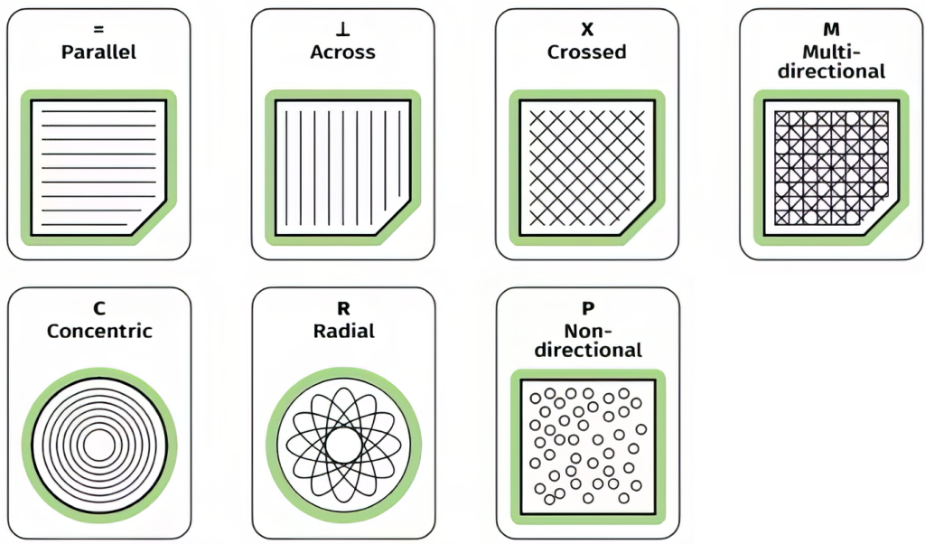
Lay is the dominant pattern of the surface and the orientation of that pattern. The manufacturing process generates the patterns and orientations of the patterns. These patterns can be parallel, perpendicular, circular, cross-hatched, radial, multi-directional, or isotropic (non-directional). Figure 9-18 displays the lay symbols that may be used.
Measurement of Roughness
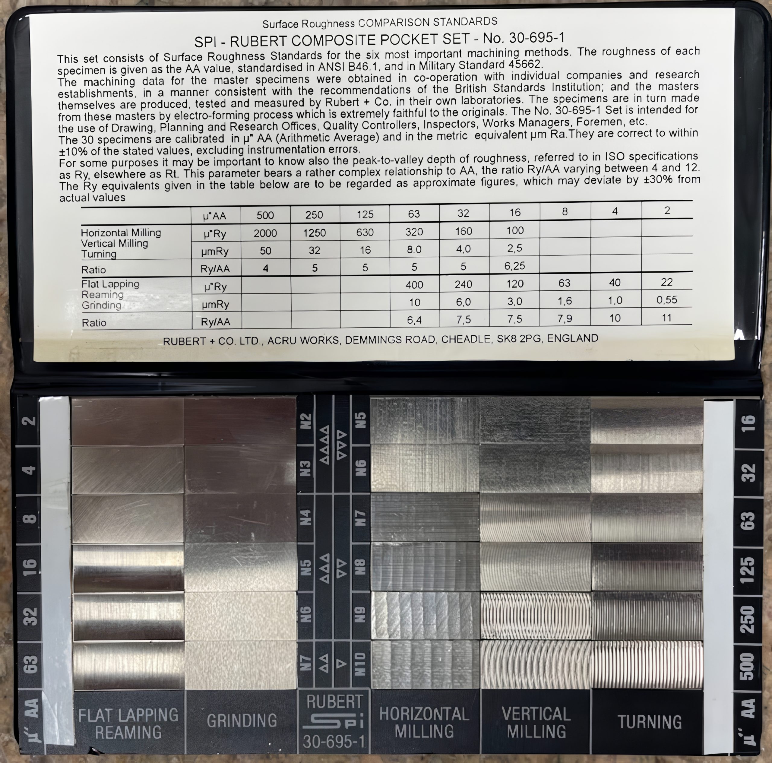
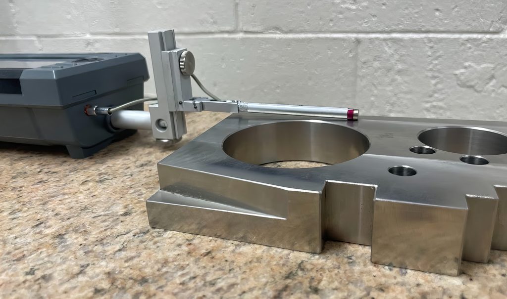
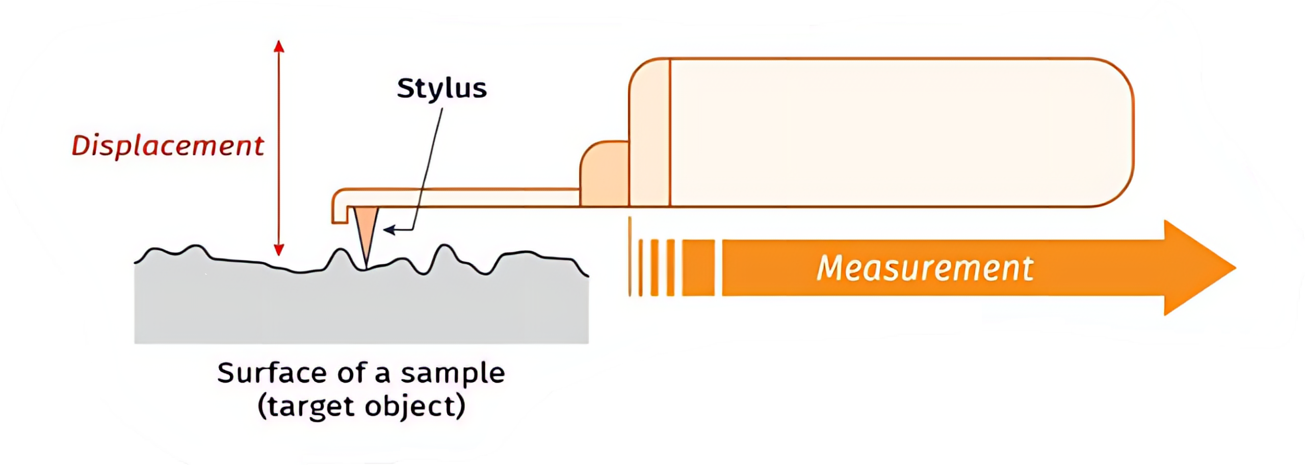
Surface roughness can be compared to a surface finish reference plate called a surface roughness comparator, as shown below in Figure 9-19. This can give a general measurement by best matching the surface roughnesses. Surface roughness is more accurately measured by an instrument known as a profilometer. The profilometer shown in Figure 9-20 uses a small stylus moving across the surface to measure the small peaks and valleys of the surface and provides an average of these measurements to provide the surface finish reading, which is illustrated in Figure 9-21. The profilometer generates a graph showing variations in surface height with changes in position.
The graph in Figure 9-22 is known as the measured surface profile. It will show not only roughness but also any wave and flatness defects that may be present.

We must remove the wave and flatness defects from the profile to examine only roughness. Without smoothing the profile, the mean line will represent surface height variation due to waviness and flatness defects. To measure roughness only, waviness is removed, and the profile line is straightened. This new, straighter line is known as the surface roughness profile, as depicted in Figure 9-23.

The roughness average (Ra) is the average of the measured height variations across the sampled length, as illustrated in Figure 9-24.

Surface Roughness Chart
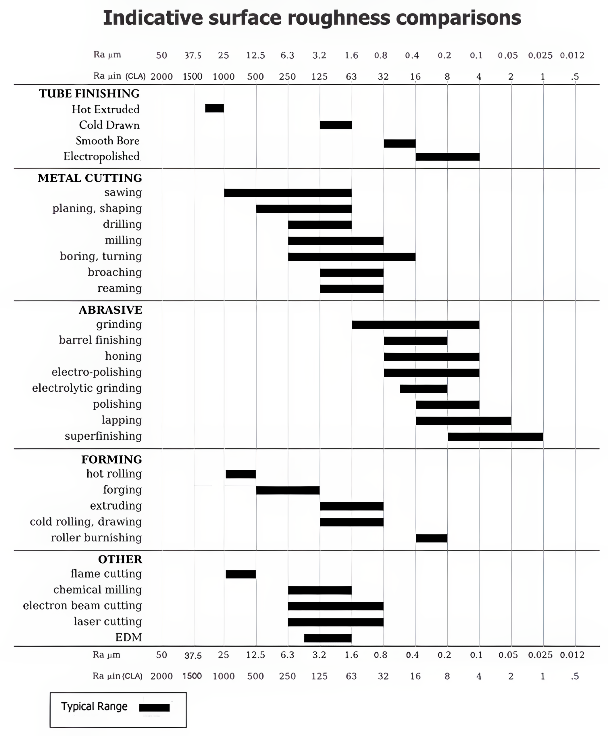
The information in Figure 9-25 represents the typical roughness values resulting from various production processes. Some examples from the chart indicate that a drilling process will provide a surface finish between 250 and 63 roughness average (Ra), while a grinding process will provide a surface finish between 63 and 4 Ra.
9.5 Geometric Dimensioning and Tolerancing (GD&T)
Feature Control Frame, Datum, and Basic Dimension
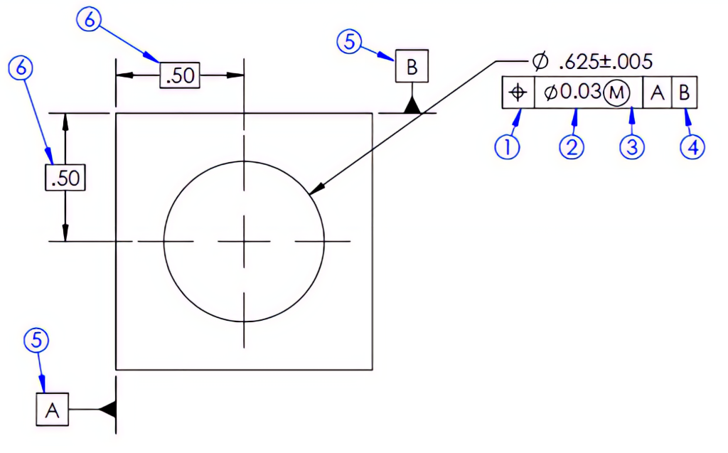
A feature control frame is used in geometric dimensioning and tolerancing to describe the conditions and tolerances of a geometric control on a part’s feature. The feature control frame consists of four pieces of information, along with the datums and basic dimension information, referenced in Figure 9-26.
- Symbol – The first box will contain the geometric symbol being identified.
- Tolerance – The next box contains the tolerance and possibly a diameter symbol.
- Modifiers – After the tolerance, a modifier may be used, such as a circled “M” or “L” for Maximum Material Condition and Least Material Condition.
- Datum Reference – This may be used to reference a surface or feature.
- Datums – Datums are features or surfaces that are used to establish a reference point or plane. The datum feature symbol is a square frame with the identifying letter inside, ending with a triangle extending from the surface.
- Basic Dimension – A basic dimension is a theoretically exact value without a tolerance. The dimension is enclosed in a rectangular frame, indicating that it does not carry the tolerance defined by the title block but uses the positional tolerance identified by the feature control frame.
You may be familiar with the term geometric dimensioning and tolerancing, or GD&T, which is a set of rules and symbols used to communicate the intent of a design, focusing on the function of the part. The use of GD&T may prevent an otherwise functional part from being rejected with traditional dimensions and tolerances. These geometric characteristics fall into four fundamental categories: size, location, orientation, and form. Study the symbols and descriptions below to relate the symbol with the characteristic it represents.

Form Tolerances
Form tolerance is a geometric tolerance that determines and controls the form or shape of the part or feature. Form tolerances do not reference datums.
Straightness
Surface straightness is a two-dimensional tolerance that controls the form of a line somewhere on the surface of the feature. Axis straightness is a tolerance that controls how much curve is allowed in the part’s axis and depicted in Figure 9-27.

Flatness

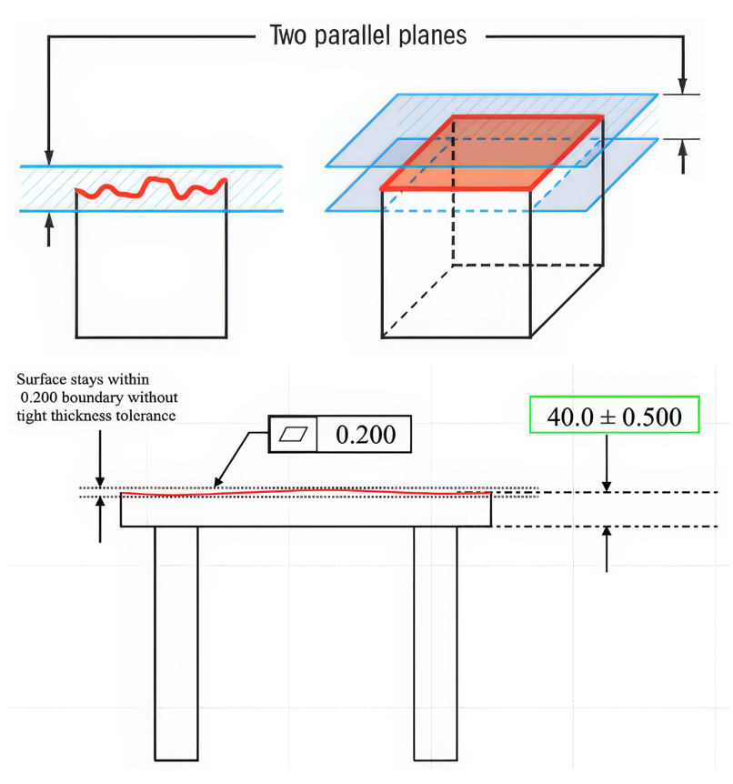
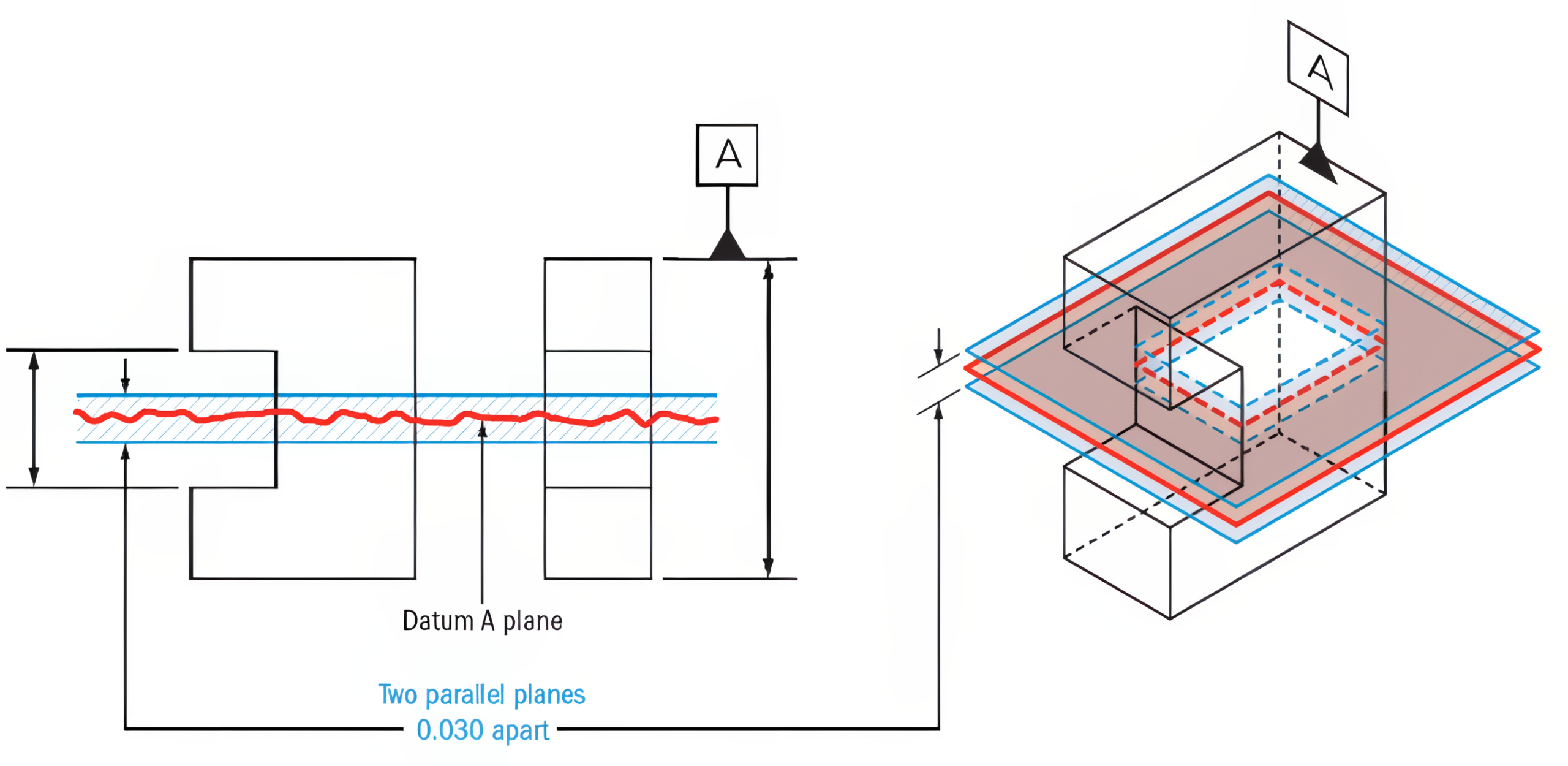
The flatness is a three-dimensional tolerance that references two parallel planes (parallel to the surface that it is called out on) that define a zone where the entire reference surface must lie. Flatness tolerance will always be less than the dimensional tolerance associated with it. This is because the feature will be flat within its size tolerance, as shown in Figure 9-28.
Circularity
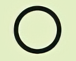
Sometimes called roundness, circularity is a two-dimensional tolerance that controls the overall form of a circle, ensuring it is not too oblong, square, or out of round. See Figure 9-29.

Cylindricity

The cylindricity symbol is used to describe how close an object conforms to a true cylinder. Cylindricity is a three-dimensional tolerance that controls the overall form of a cylindrical feature to ensure that it is round enough and straight enough along its axis, as shown in Figure 9-30.

Profile Tolerances
Profile tolerance is a geometric, three-dimensional tolerance that defines a boundary around which the surface must stay within. Profile tolerances can use all of the four fundamental categories listed above.
Line Profile
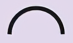
Profile of a line describes a tolerance zone around any line in any feature, usually of a curved shape. The profile of a line is a two-dimensional tolerance range that can be applied to any linear tolerance. View Figure 9-31.
Profile Surface
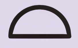
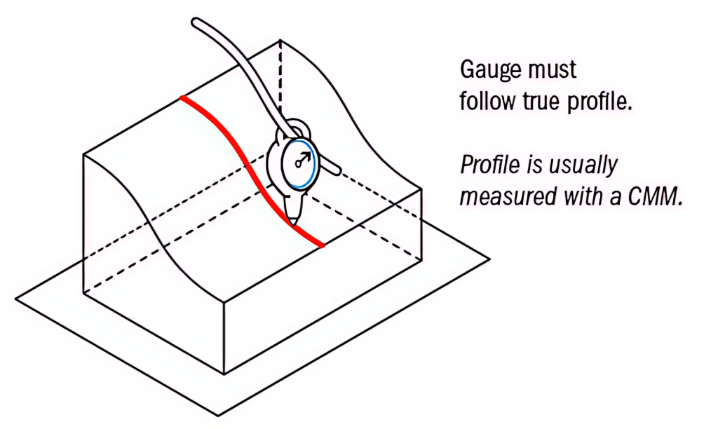
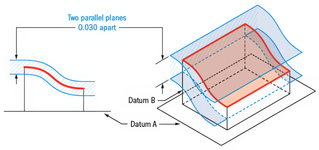
Profile of a surface describes a three-dimensional tolerance zone around a surface, which is usually an advanced curve or shape. Profile controls all the points along the surface within a tolerance range that directly mimics the designed profile. Any point on the surface would not be able to vary inside or outside by more than the surface profile tolerance, as shown in Figure 9-32.
Orientation Tolerances
Angularity
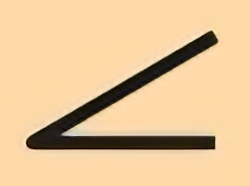
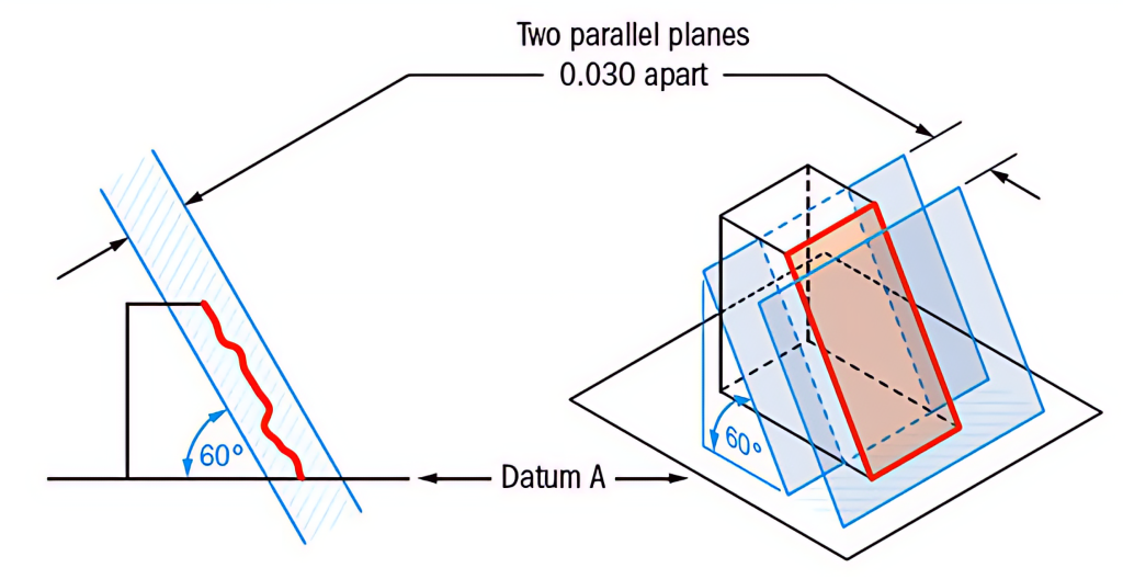
Angularity is the symbol that describes the specific orientation of one feature (datum) to another at a referenced angle. See Figure 9-33.
Perpendicularity
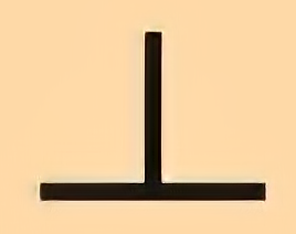
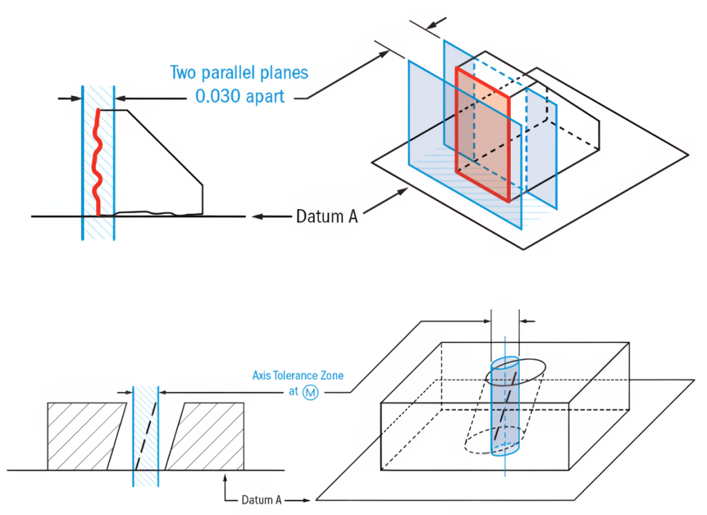
Surface perpendicularity is a tolerance that controls perpendicularity between two 90° surfaces or features. Surface perpendicularity is controlled with two parallel planes acting as its tolerance zone. Axis perpendicularity is a tolerance that controls how perpendicular a specific axis is to a reference (datum). Axis perpendicularity is controlled by a cylinder around a theoretically perfectly parallel axis. See Figure 9-34.
Parallelism
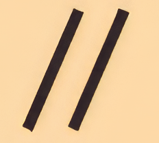
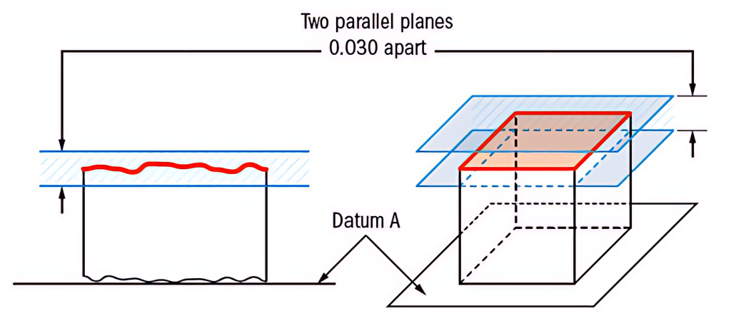
Surface parallelism is a tolerance that controls parallelism between two surfaces or features, one being a datum. The surface form is controlled similarly to flatness with two parallel planes acting as its tolerance zone, as illustrated in Figure 9-35.
Location Tolerances
Location tolerance is a geometric tolerance that determines the location (true position) of a feature in relation to a datum.
Position

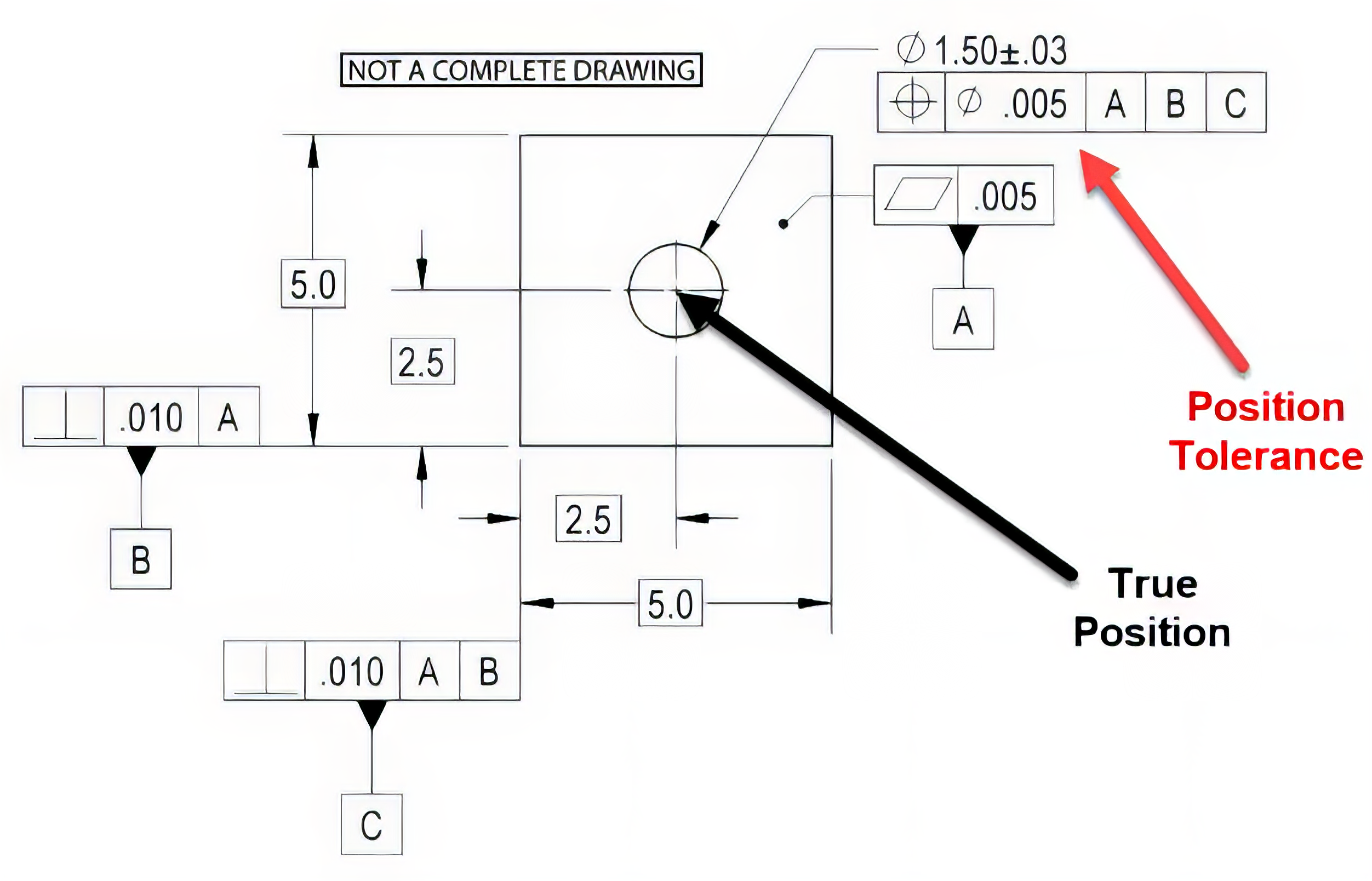
The true position, or just position as the ASME standard calls it, is defined as the total permissible variation that a feature can have from its “true” position. See Figure 9-36.
Concentricity

The ASME Y14.5 standard was last updated in 2018, and one of the substantial changes was the elimination of the concentricity GD&T control but still may be found on drawings. Previous versions of the standard recommended using runout (the amount a circular feature varies when rotated around an axis) or position controls instead of concentricity. The 2009 version of the Y14.5 GD&T standard defines concentricity as “the condition where the median points of all diametrically opposed elements of a surface of revolution (or the median points of correspondingly located elements of two or more radially disposed features) are congruent with a datum axis (or center point).” See Figure 9-37 below.

Symmetry
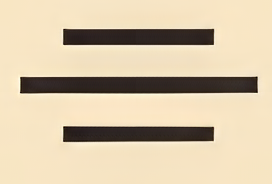
GD&T symmetry is a three-dimensional tolerance that is used to ensure that two features on a part are uniform across a reference surface known as a datum plane, as shown in Figure 9-37. Along with concentricity, symmetry has also been removed from the latest 2018 ASME Y14.5 standard, although the tolerance may still be found on some drawings.
Runout Tolerances
Runout tolerance is a geometric tolerance that specifies the amount a circular feature may vary when rotated.
Circular Runout
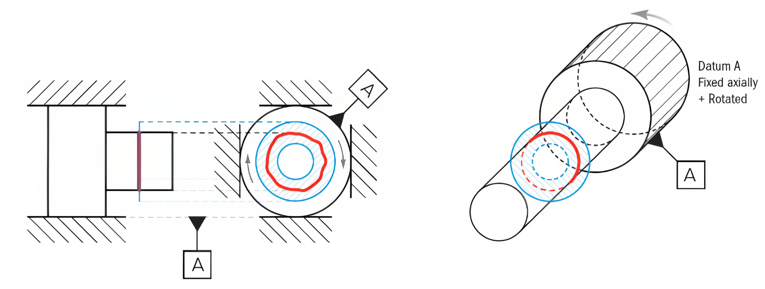
Runout is how much one given reference feature or features vary with respect to another datum when the part is rotated 360° around the datum axis. It is essentially a control of a circular feature and the amount of variation it has with the rotational axis. View Figure 9-39.
Total Runout
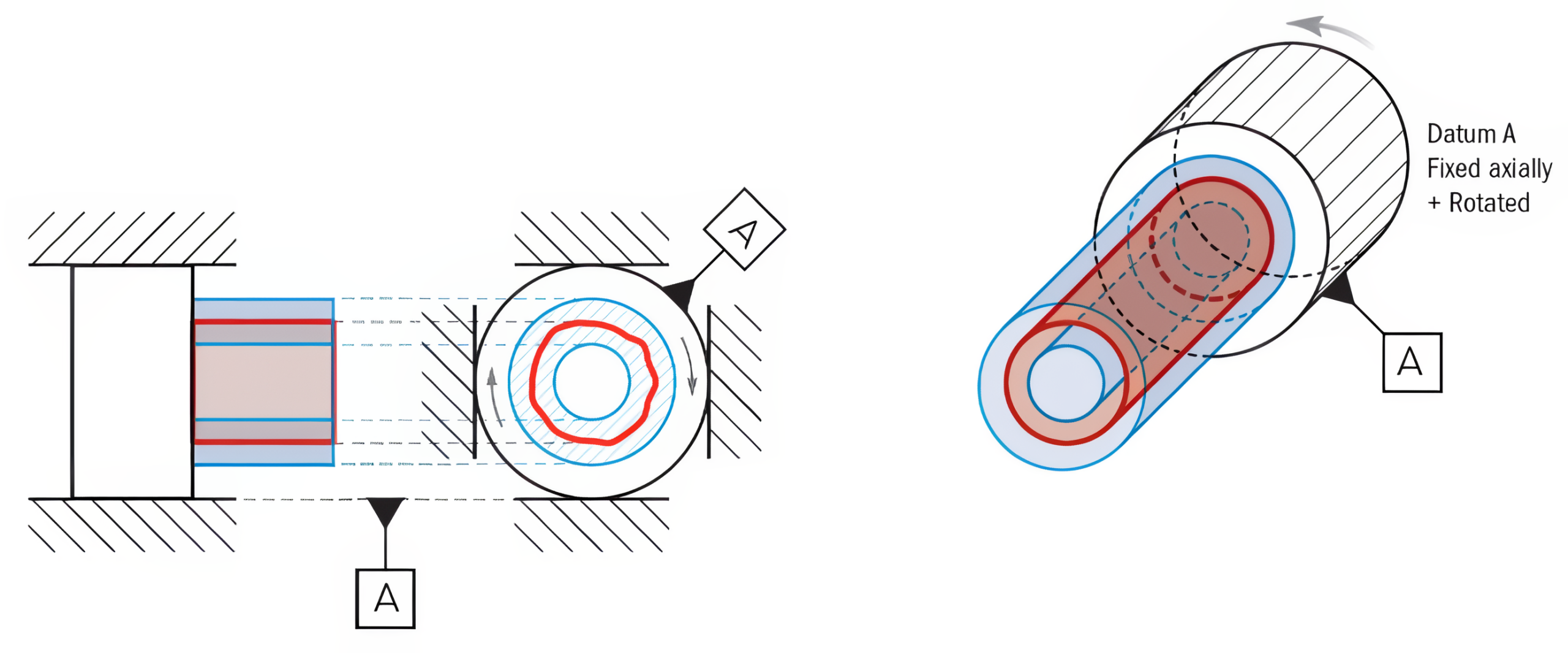
Total runout is how much one entire feature or surface varies with respect to a datum when the part is rotated 360° around the datum axis. Total runout controls both the amount of variation in the surface as the part is rotated and the amount of variation in the axial dimension, illustrated in Figure 9-40.
Material Condition Symbols
Earlier chapters introduced a feature’s Maximum Material Condition (MMC) and Least Material Condition (LMC). These conditions are used in the feature control frame with a circled “M” for Maximum Material Condition and “L” for Least Material Condition. When these conditions are placed in the feature control frame, they are referred to as modifiers.
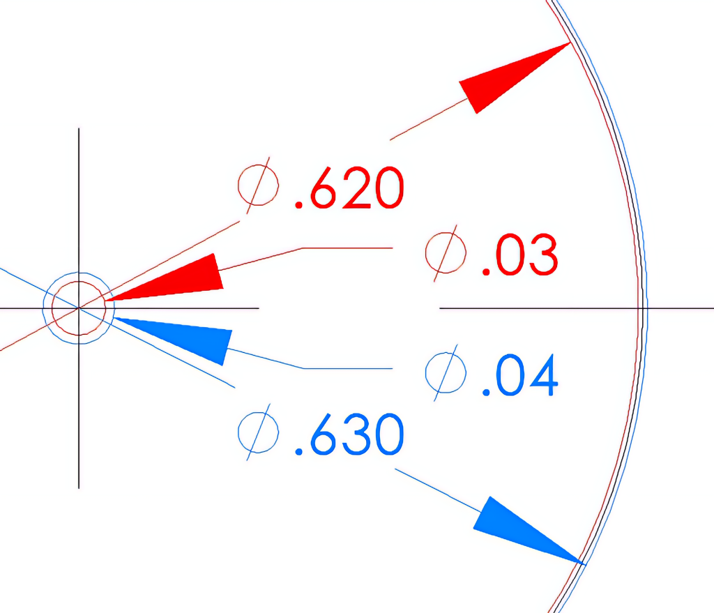
In the Figure 9-26 feature control frame example, the ⌀0.625 hole has a positional tolerance of ⌀0.03 when the hole is at its MMC of ⌀0.620. This means that when the hole is at its smallest allowable size (MMC), the center point position of the hole must be within a ⌀0.03 circle of the basic dimension location. As the hole size moves away from its MMC (becomes larger), the tolerance zone will also increase by the same amount. This is done because as the hole size increases, the position may deviate by the same amount, and the feature will still function. Figure 9-41 illustrates the ⌀0.03 center location zone with the hole size at ⌀0.620 (MMC) in red and the ⌀0.04 center location zone when the hole is at its largest allowable size of ⌀0.630 (LMC) in blue.
Projected Tolerance Zone
A third modifier that may be used is a circled “P” for the projected tolerance zone. In GD&T, the projected tolerance zone symbol indicates the tolerance zone of a feature that is to be assessed beyond the surface. In most cases, this symbol verifies that a fastener will still clear a mating part during assembly regardless of how thick the assembling part is and the orientation in which the fastener is assembled. See Figure 9-42.

For further information on Geometric Dimensioning and Tolerancing please visit: https://www.gdandtbasics.com/
Learning Activities
Exercise 9.6-1
Exercise 9.6-2
Exercise 9.6-3
Exercise 9.6-4
References:
Barsamian, M. A., & Gizelbach, R. (2022). Machine trades print reading. Goodheart-Willcox.
Schultz, R. L., & Smith, L. L. (2012). Blueprint reading for machine trades (7th ed.). Pearson.
Images:
All images by Mark Lorier and licensed under CC BY-NC 4.0 except where otherwise noted.
Figure 9-11 “Basics-of-Surface-Finish_components2-932×800” by GDandTBasics.com is reused with permission. All rights reserved. Access for free at https://www.gdandtbasics.com/basics-of-surface-finish/
Figure 9-18 “Surface-Finish-Fig-6_Symbols_CloseUp2” by GDandTBasics.com is reused with permission. All rights reserved. Access for free at https://www.gdandtbasics.com/basics-of-surface-finish/
Figure 9-21 “Profilometer-Fig1_Profilometer-Contact” by GDandTBasics.com is reused with permission. All rights reserved. Access for free at https://www.gdandtbasics.com/what-is-a-profilometer/
Figure 9-22 This image is derivative of “Surface-Finish-Fig-23_surface-profile-mean-line2” by GDandTBasics.com and reused with permission. All rights reserved. Access for free at https://www.gdandtbasics.com/basics-of-surface-finish/
Figure 9-23 This image is derivative of “Surface-Finish-Fig-23_surface-profile-mean-line2” by GDandTBasics.com and reused with permission. All rights reserved. Access for free at https://www.gdandtbasics.com/basics-of-surface-finish/
Figure 9-24 “Surface-Finish-Fig-4_Ra2” by GDandTBasics.com is reused with permission. All rights reserved. Access for free at https://www.gdandtbasics.com/basics-of-surface-finish/
Figure 9-25 “SurfaceFinishRoughnessByProcess” by GDandTBasics.com is reused with permission. All rights reserved. Access for free at https://www.gdandtbasics.com/basics-of-surface-finish/
Figure 9-27 “Snag_59d7b2d-768×429” and “Snag_59e15b8-768×247” by GDandTBasics.com are reused with permission. All rights reserved. Access for free at https://www.gdandtbasics.com/basics-of-surface-finish/
Figure 9-28 “Flatness-Tolerance-Zone” and “Flatness-Example1-Table-with-gdt” by GDandTBasics.com are reused with permission. All rights reserved. Access for free at https://www.gdandtbasics.com/basics-of-surface-finish/
Figure 9-29 “Circularity-Tolerance-Zone” by GDandTBasics.com is reused with permission. All rights reserved. Access for free at https://www.gdandtbasics.com/basics-of-surface-finish/
Figure 9-30 “cylindricityTolerance-Zone” by GDandTBasics.com is reused with permission. All rights reserved. Access for free at https://www.gdandtbasics.com/basics-of-surface-finish/
Figure 9-31 “Profile-of-line-gauging” by GDandTBasics.com is reused with permission. All rights reserved. Access for free at https://www.gdandtbasics.com/basics-of-surface-finish/
Figure 9-32 “Profile-of-surface-tolerance-zone” by GDandTBasics.com is reused with permission. All rights reserved. Access for free at https://www.gdandtbasics.com/basics-of-surface-finish/
Figure 9-33 “Angularity-Tolerance-Zone” by GDandTBasics.com is reused with permission. All rights reserved. Access for free at https://www.gdandtbasics.com/basics-of-surface-finish/
Figure 9-34 “04-Perpendicularity-surface-tolerance-zone” and “05-Perpendicularity-axis-tolerance-zone” by GDandTBasics.com are reused with permission. All rights reserved. Access for free at https://www.gdandtbasics.com/basics-of-surface-finish/
Figure 9-35 “Parallelism-Tolerance-Zone” by GDandTBasics.com is reused with permission. All rights reserved. Access for free at https://www.gdandtbasics.com/basics-of-surface-finish/
Figure 9-36 “Figure1-1024×740” by GDandTBasics.com is reused with permission. All rights reserved. Access for free at https://www.gdandtbasics.com/basics-of-surface-finish/
Figure 9-37 “Snag_aa599d8-1024×349” by GDandTBasics.com is reused with permission. All rights reserved. Access for free at https://www.gdandtbasics.com/basics-of-surface-finish/
Figure 9-38 “Symmetry-Tolerance-Zone” by GDandTBasics.com is reused with permission. All rights reserved. Access for free at https://www.gdandtbasics.com/basics-of-surface-finish/
Figure 9-39 “runout-Tolerance-Zone” by GDandTBasics.com is reused with permission. All rights reserved. Access for free at https://www.gdandtbasics.com/basics-of-surface-finish/
Figure 9-40 “01-Total-Runout-Tolerance-Zone1” by GDandTBasics.com is reused with permission. All rights reserved. Access for free at https://www.gdandtbasics.com/basics-of-surface-finish/
Figure 9-42 This image is derived from “Figure-3_Applying-Projected-Tolerance-Method-1_v2” by GDandTBasics.com is reused with permission. All rights reserved. Access for free at https://www.gdandtbasics.com/basics-of-surface-finish/
Unnumbered images are all derived from “GD&T Basics Wall Chart PDF” by GDandTBasics.com are reused with permission. All rights reserved. Access for free at https://www.gdandtbasics.com/gdt-symbols-chart/

