8. Tolerance on Dimensions
8.1 Introduction
Learning Objectives
- Define tolerance terminology
- Apply mathematical concepts to determine tolerances on dimensions
- Determine tolerances on dimensions
- Determine limits on dimensions
- Describe how tolerances affect mating parts
Terms
- Tolerance
- Bilateral tolerance
- Equal bilateral
- Unequal bilateral
- Unilateral tolerance
- Limits
- Single-limit dimensioning
- Specified tolerance
- Unspecified tolerance
- Material condition
- Interference fit
- Clearance fit
- Reference dimension
Dimension tolerances are critical in ensuring that products meet the required specifications and perform their intended functions. Each dimensioned value of a part’s sizes and features will have some allowable variance in size. It is important to comprehensively understand dimension tolerances, their significance, and their application in various industries.
This chapter will explore dimension tolerances and their connection to a product’s intended functionality and quality. It will also investigate various tolerances, including bilateral, unilateral, and limit tolerances, and their definitions and understanding in engineering drawings.
8.2 Tolerance
Tolerance is the allowable variation or deviation from a specified dimension, measurement, or other characteristic of a product or component. Because it is impossible for a part to be produced to an exact theoretical size, providing a tolerance for the size is necessary. It defines the acceptable range within which a part or feature can deviate from its intended design while maintaining its functionality and meeting the required specifications. Tolerances are crucial in engineering and manufacturing to ensure proper fit, assembly, and performance of parts and facilitate interchangeability and quality control. Tolerances are typically specified on engineering drawings or technical documentation and expressed as numerical values, limits, or a combination. Tolerances are vital in determining manufactured products’ precision, accuracy, and interchangeability.
The amount of tolerance on any part will directly impact the manufacturing cost. A designer must be careful not to apply a closer tolerance value than is necessary for the part function, as this will unnecessarily increase the cost due to the extra time and often extra processes necessary to meet the closer sizes.
8.3 Bilateral Tolerance
When a tolerance is allowed to deviate from the dimension in both the positive and negative directions, it is known as a bilateral tolerance. When the tolerance is equal in both directions, it is an equal bilateral, or symmetrical, tolerance. The example in Figure 8-1 has an equal bilateral tolerance of ±0.002. In this example, the measured size may fall within the range of 0.002 above the dimensioned size to or 0.002 below the dimensioned size. In the Figure 8-1 example of the 2.000 dimension, the allowable size may range from 1.998 to 2.002, giving a total tolerance range of 0.004.

When a dimension’s tolerance is bilateral, moving in both positive and negative directions but with different tolerance values, it is called an unequal bilateral tolerance. The tolerance in Figure 8-2 value may be anywhere from larger than the dimension by 0.001 to smaller by 0.002. In this 2.000 example, the size may range from 1.998 to 2.001 for a total tolerance range of 0.003.

When the tolerance of a dimension moves only in one direction, having a zero value in either its positive or negative direction, this is called unilateral tolerance. In the example shown in Figure 8-3, the size tolerance may not move above the dimension value but can move below the dimension value by 0.005. In this 2.000 example, the allowable size may range between 1.995 and 2.000 for a total tolerance range of 0.005.

8.4 Limit Dimensioning
Dimensional limits are the maximum and minimum allowable sizes of the dimension. The maximum and minimum permissible sizes will be displayed in place of plus or minus values. With limit dimensioning, the maximum or high limit will appear above the minimum or low limit value. Figure 8-4 displays a limit dimensioning example. In this example, 2.002 is the high limit, and 1.998 is the low limit, giving a total tolerance range of 0.004.

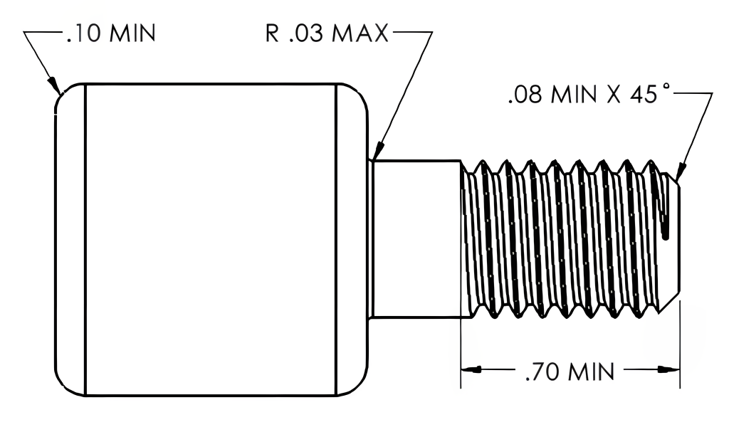
Single-limit dimensioning will use only one limit value, the minimum or the maximum, unlike limit dimensioning, where a range of acceptable variation is displayed. Single-limit dimensioning specifies a single value representing a dimension’s minimum or maximum limit. The minimum limit is denoted by its abbreviation “MIN,” while the maximum limit is defined by “MAX.”
Single-limit dimensioning is used when there is a need to control only one side of the acceptable variation for a dimension. It may be employed when the other side of the tolerance range is not critical or when there is a specific requirement to limit the variation in one direction while allowing more flexibility in the other direction. A single-limit dimension is often used in depths of holes or threads and radii or chamfer values. In Figure 8-5, single-limit dimensions are used for minimum and maximum values on radii, chamfer, and thread length values.
8.5 Unspecified Tolerances
The examples above are known as specified tolerances. Specified tolerances appear with the specific dimensioned value and are directly applied to that value. Specified tolerances are not shared with any other dimension.
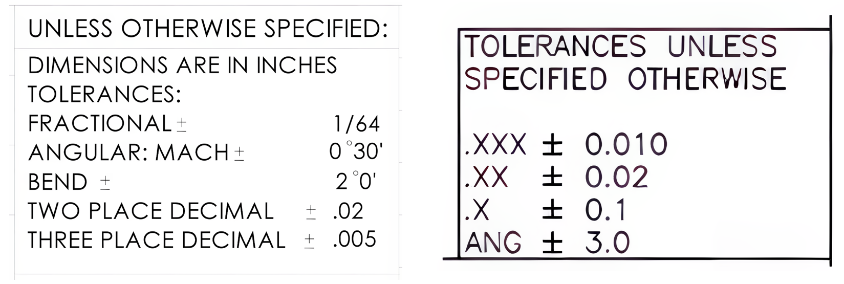
When a dimension does not have a specified tolerance, the tolerance value from the print’s tolerance block will be applied, known as unspecified tolerances. In the print’s tolerance block, you’ll see the applicable tolerances outlined according to the type of dimension you’re working with—whether it’s fractional, angular, metric, or based on decimal places for either decimal inch or metric values. Figure 8-6 displays examples of tolerances applied to all dimensions without a specified tolerance.
8.6 Material Condition
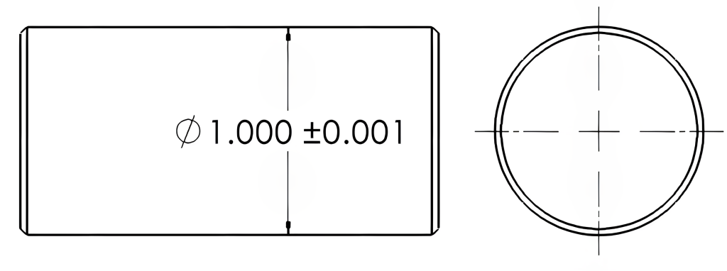
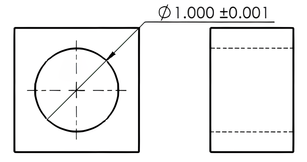
Material condition refers to the maximum or least amount of material allowed within the tolerance of a feature size. These are referred to as Least Material Condition (LMC) and Maximum Material Condition (MMC). For an external feature, Least Material Condition will be the smallest size allowed, and the largest size allowed is the Maximum Material Condition. For an internal feature, the Least Material Condition will be the largest size allowed, and the smallest size allowed will be the Maximum Material Condition. To better understand this, consider what happens as material is removed from the surface. As material is removed from an outside surface, such as an outside diameter, the part size will get smaller.
Conversely, as material is removed from an inside surface, such as a hole, the hole size will become larger. When machining these features, you aim to be material-safe at the MMC dimension. No further material can be removed at the LMC dimension. In the Figure 8-7 example below, the MMC of the shaft is 1.001, and the LMC is 0.999. In Figure 8-8 below, the MMC of the hole would be 0.999, and the LMC of the hole would be 1.001.
8.7 Clearance and Interference
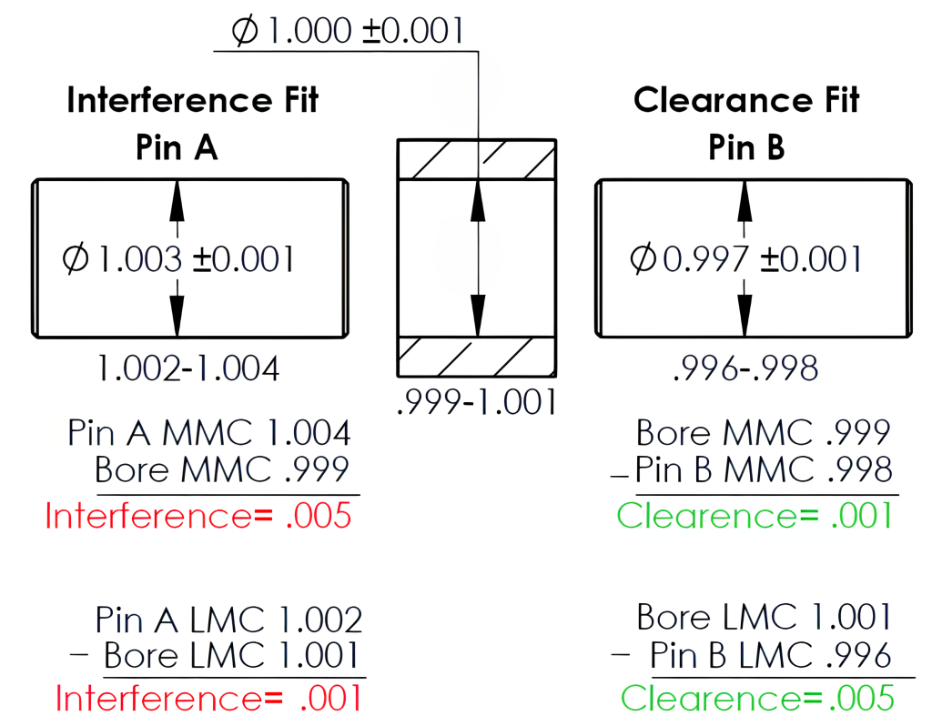
When creating a print, it’s essential to consider the sizes and tolerances involved thoughtfully. An interference fit occurs when a part is larger than the part it is to be fit into; this is also referred to as a press fit. A clearance fit occurs when a part is smaller than the part it is to be fit into; this is also called a slip fit. Maintaining the desired design function of components requires careful attention to all acceptable dimensions. In the example shown in Figure 8-9, the sizes and tolerances for the hole component (shown in the middle of the figure) and Pin A must ensure they maintain the interference fit as intended. The dimensions and tolerances are compared in the Pin A interference fit at MMC and LMC.
On the other hand, if our goal is to achieve clearance or slip fit, we can consider Pin B. Its size and tolerance have been carefully chosen to guarantee adequate clearance, regardless of allowable size variations.
Standard fit sizes for both inch and metric values based on the basic part size and fit required have been established and are often referenced by the designer. These values are available in various reference books, such as the Machinery Handbook. The Figure 8-9 clearance fit example examines scenarios in which parts are created at MMC and LMC while maintaining their desired clearance fit.
8.8 Tolerance Accumulation
As each drawing dimension will have a tolerance assigned, it is essential not to have a feature dimensioned more than once, making the drawing over-dimensioned. Over-dimensioning is avoided because a feature may contain more than one tolerancing option. Because of this, many sizes must be calculated from other dimensions. When dimensions are calculated, the tolerance of each dimension used accumulates as well. Even when dimensions are subtracted, the tolerances of each dimension used to obtain the feature size will accumulate.
An earlier chapter discussed the different methods of dimensioning used below. This chapter examines how these various methods can affect the tolerances of the four lengths and the overall length of the object.
Figure 8-10 uses datum-dimensioning, with each dimension referenced from the left edge. In this datum-dimensioned example, each measurement from the datum end maintains the ±0.01 tolerance. This example means the 1.00, 2.00, 3.00, and 4.00 all have a tolerance value of ±0.01. To obtain the value for length B, the 1.00 is subtracted from 2.00. Because the two dimensions used each have a tolerance of ±0.01, these combine for a ±0.02 tolerance on length B. The addition of these tolerances is illustrated in the equations below. If the 2.00 is at its MMC and the 1.00 at its LMC, length B will be 1.02. Conversely, if the 2.00 is at its LMC and the 1.00 is at MMC, then length B will equal 0.98. This concept will repeat for lengths C and D.
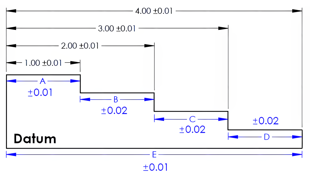
Figure 8-11 uses a chain-dimensioned example; the distance of each length is toleranced independently. The overall distance would need each dimension added together, making the overall length a tolerance of ±0.04. As illustrated in the equations below, adding the MMCs of each length results in the overall length having a +0.04 tolerance, and adding the LMCs of each length will result in an overall length of -0.04. Each combination of lengths added together would accumulate the ±0.01 tolerance as well.
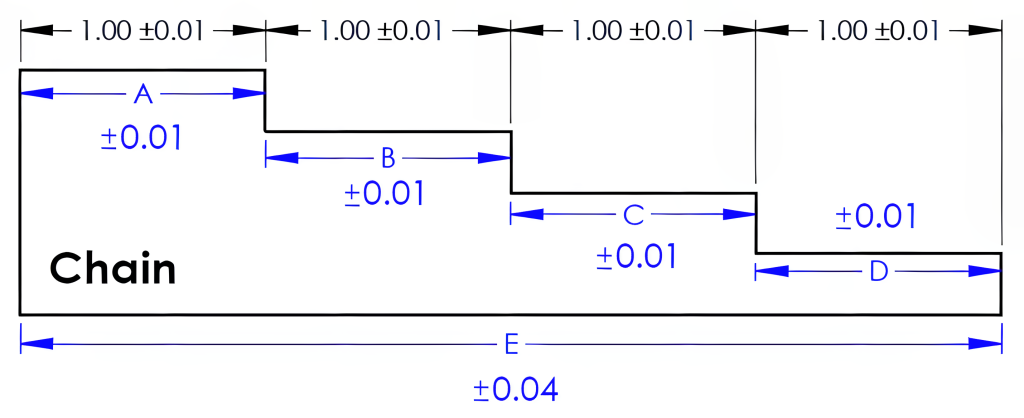
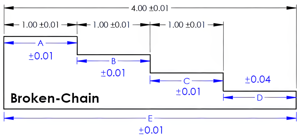
Figure 8-12 uses broken-chain dimensioning. In this example, length D is left undimensioned. To obtain the length of D, lengths A, B, and C are to be subtracted from the overall length E. The tolerance of each length will stack together in length D for a ±0.04 tolerance for this dimension. The formula below shows the LMC of lengths A, B, and C subtracted from the MMC of the overall length (E), resulting in a 1.04 maximum length for D. The calculation for the minimum length for D begins with the LMC for the overall length and then subtracts the maximum lengths of A, B, and C for a 0.96 minimum length for D.
8.9 Reference Dimension
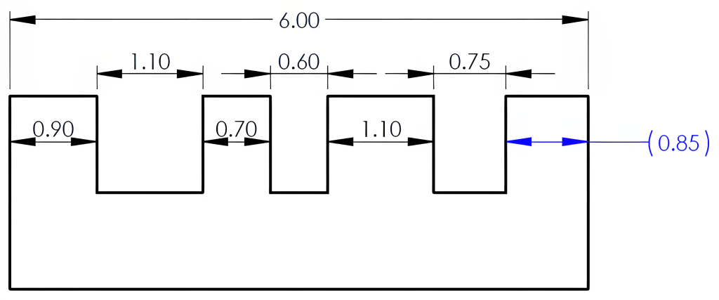
In these scenarios above, notice that if all four lengths and the overall length dimensions were to be included, the tolerances would interfere with each other. If a drawing contains all these dimensions, it would create what is referred to as an over-dimensioned drawing. However, these missing dimensions may be included without carrying a tolerance. These non-tolerance dimensions are known as reference dimensions. The drafter will indicate the dimension as a reference by enclosing the value in parentheses, or the value will be followed by the abbreviation REF, as shown in Figure 8-13. Reference dimensions can be useful in a variety of ways, such as in identifying stock sizes.

The reference dimension example in Figure 8-14 is included to help the reader identify the 0.85 dimension without calculating the value. However, the tolerance that would accumulate in calculating this value from the other dimensions will still be applied. Therefore, these reference dimensions should not be inspected, as they do not carry tolerance values.
Learning Activities
Exercise 8.9-1 Tolerance
Exercise 8.9-2 Tolerance
Exercise 8.9-3 Tolerance
Exercise 8.9-4 Tolerance
Exercise 8.9-5 Tolerance
References:
Barsamian, M. A., & Gizelbach, R. (2022). Machine trades print reading. Goodheart-Willcox.
Schultz, R. L., & Smith, L. L. (2012). Blueprint reading for machine trades (7th ed.). Pearson.
TLDR Technologies. (2024). Simplified AI. [Large language model]. https://simplified.com/ai-writer
Images:
All images by Mark Lorier and licensed under CC BY-NC 4.0 except where otherwise noted.

