7. Title Blocks
7.1 Introduction
Learning Objectives
- Describe the information found in a title block
- Identify other elements of information found on a print
- Identify the current drawing revision and the changes
- Apply tolerance information found in the title blocks
- Differentiate between specified and unspecified tolerances
- Define tolerance terminology
Terms
- Title block
- Drawing number
- Part number
- Scale
- Revision
- Zone
Understanding the title block of a print is essential for interpreting and understanding important information about the drawing. The title block is a standardized section located in the lower right corner of the print and contains crucial details about the drawing. It typically includes information such as the title of the drawing, the drawing number, the revision number, the scale of the drawing, the date of creation or revision, the material, and the name of the drafter or designer. The title block is a reference point for identifying and organizing drawings, ensuring accuracy, and tracking revisions. Familiarizing yourself with title block information will help ensure you understand all the necessary information accurately.
7.2 Print Formats
It’s important to note that the layout of the title block and certain elements can vary among companies. Some organizations follow established drafting standards from respected bodies like the ANSI or ISO. In contrast, others may opt for a more tailored approach that suits their needs. Regardless of the chosen style, you can always expect that all drawings will include the essential information required to understand each part.
7.3 Print Sizes
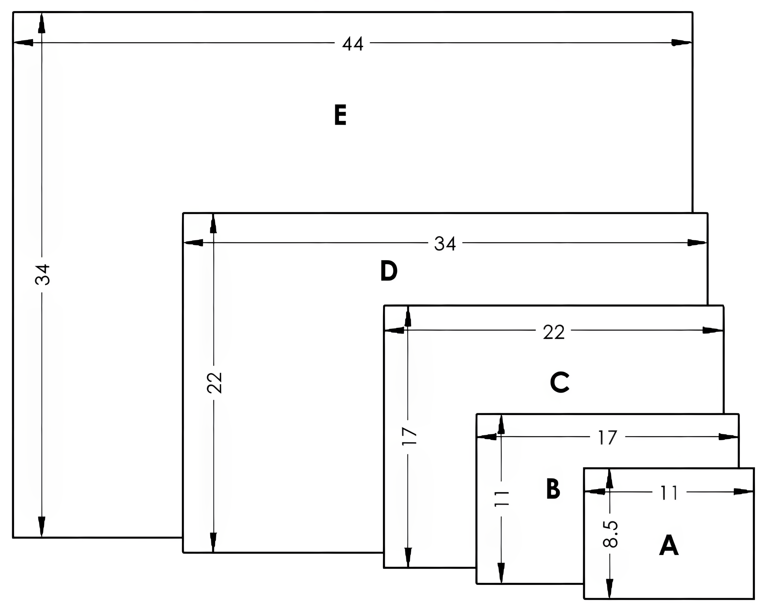
The sizes of the prints are identified by standards as well. Whether in digital form or physical paper, size codes are identified by letters A through E for decimal-inch drawings or A4 through A0 for metric drawings. The print size will depend on the space necessary to communicate the information effectively. A small, simple part may fit on a small sheet, while a large or complex part or assembly may require more space. The initial size is a standard letter format measuring 8.5 x 11 inches, and from there, the dimensions will increase, with the previous length becoming the new width, as shown in Figure 7-1.
| Inch
A: 8.5 x 11 inches B: 11 x 17 inches C: 17 x 22 inches D: 22 x 34 inches E: 34 x 44 inches |
Metric
A4: 210 x 297 mm A3: 297 x 420 mm A2: 420 x 594 mm A1: 594 x 841 mm A0: 841 x 1189 mm |
|---|

7.4 Title Block Information
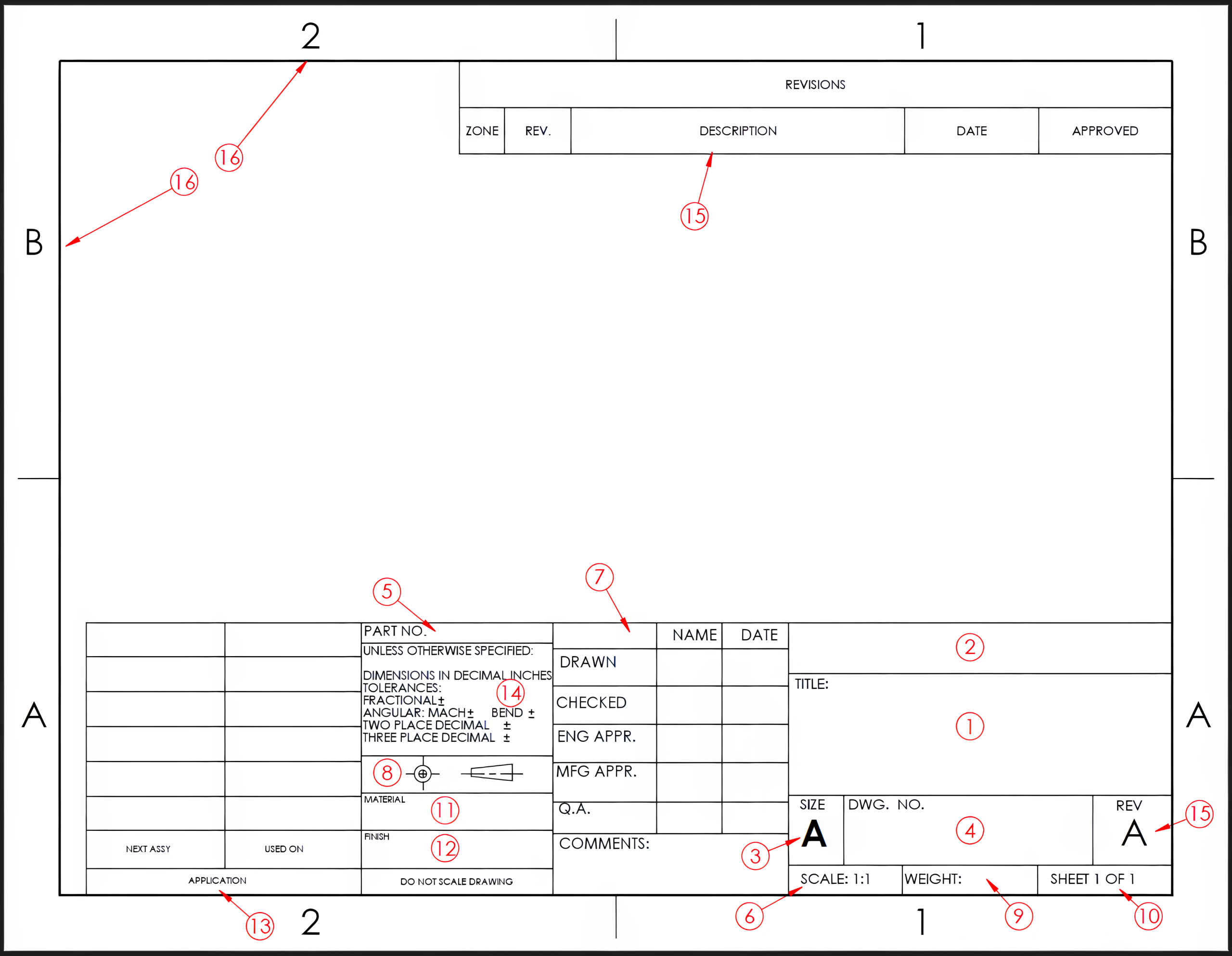
The title block is the rectangular area in the lower right containing several information boxes. Some of the information includes the company name and/or logo, drawing and part number, designer, scale, and drawing dates. The boxes keep the project information organized and easily located. Figure 7-2 identifies common title block features with their definitions.

- Part Title – The title is a descriptive name given to the drawing, typically the largest box in the title block.
- Company Information – The name of the company responsible for the drawing will also appear in a larger box in the title block. Often, a logo for the company will be displayed as well.
- Size – The size block displays the letter of the sheet size of the print.
- Drawing Number – The drawing number is a numbering system the company uses to aid in filing and tracking the drawing.
- Part Number – A part number may be used to identify a specific part, such as in an assembly parts list.
- Scale – The scale displays the proportion of the drawing compared to the object. When the part is too large to fit on the sheet, the drawing may be reduced to ½, ¼, ⅛, etc., of the part size. When the part is smaller than the sheet, the drawing may also be increased proportionally. The ratio displayed in the scale box is arranged by the size of the drawing followed by the size of the part. This can be called the “DO” scale, where “D” is the drawing, and “O” is the object (DRAWING:OBJECT). A scale of 1:2 indicates that the drawing is “1” and the actual object is “2,” or the drawing is half the size of the part. A scale of 2:1 indicates the drawing is twice the size of the part. When the part and drawing are the same size, the scale can be indicated as 1:1, or “Full” may be displayed in the scale box. The drawing size may be made to best fit the sheet size without being a nominal or basic proportion. The scale box will display “NTS” for “Not To Scale” if the drawing does not follow a basic proportional size.
- Drawn – This contains the name or initials of the drafter and the date of the drawing, as well as any other individuals involved with the project.
- Projection – Projection identifies whether the drawing is a first-angle or third-angle projection. This may be indicated with the projection cone or written out.
- Weight – Weight may be used to indicate the weight of the finished part when required.
- Sheet – The sheet box displays the current and total number of sheets in that drawing set.
- Material – The material section identifies the material specifications required.
- Finish – The finish box is used to display any part finish specifications. Finish specifications may also be used for some regions of the part, and they are indicated with leader lines for those areas.
- Application – The application block is used to identify the assemblies on which the part is used.
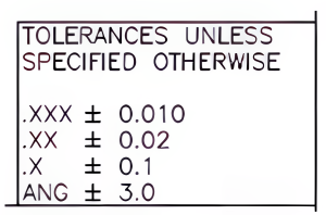
- Tolerance – The tolerance box displays the tolerance or amount of variation allowed on the dimension values. These tolerances apply to dimensions that do not have a tolerance specified with a particular dimension. These tolerances are applied by the type of dimension, fractional, angular, or the number of decimal places displayed on decimal inch or metric values. See Figure 7-3.

Figure 7-3. The tolerance box displays the amount of tolerance allowed for dimensions not otherwise specified. With the tolerance block used in Figure 7-3, a two-place dimension of 2.00 allows for a ±0.02 tolerance, indicating that any measurement from 1.98 to 2.02 is permissible. For a three-place dimension of 2.000, acceptable measurements must fall within the range of 1.990 to 2.010.
- Revision – Revisions are changes made to the drawing from the original version. These revisions can be to correct errors, improve the design, or make modifications due to a change in the manufacturing process to reduce expense. The revision level or letter is indicated in the lower right title block. The changes that have been made will typically be located in the upper right of the sheet, with the matching revision letter often in a triangular shape indicated at the location of the change. You must be sure you are working with the latest revision level to ensure the correct part is being produced. If the drawing is released as a new drawing with no revision, a dash can be placed in the revision box. Some companies may instead use the letter “A” in the revision box to release the initial drawing. Both are acceptable.
- Zones – Sheet zones help locate a particular detail or view. They are beneficial when working with larger sheets.
Learning Activities
Exercise 7.4-1
Exercise 7.4-2
Exercise 7.4-3
References:
Barsamian, M. A., & Gizelbach, R. (2022). Machine trades print reading. Goodheart-Willcox.
Schultz, R. L., & Smith, L. L. (2012). Blueprint reading for machine trades (7th ed.). Pearson.
Images:
All images by Mark Lorier and licensed under CC BY-NC 4.0 except where otherwise noted.

