6. Print Dimensions
6.1 Introduction
Learning Objectives
- Determine overall part sizes for stock selection
- Apply mathematical concepts to interpret print dimensions
- Determine part feature locations
- Interpret angular measurements on prints
- Calculate missing dimensions
- Interpret part feature sizes
- Identify critical dimensions
Terms
- Radius
- Diameter
- Typical dimensions
- Angular dimensioning
- Degrees, Minutes, Seconds (DMS)
- Decimal degree
- Linear dimensions
- Included angle
- Bolt circle
- Concentric
Interpreting and calculating dimensions on prints is a vital skill in various industries. Interpreting and calculating dimensions for overall stock, missing sizes, radii, diameter, and angular features are common requirements in many drawings.
It requires a thorough understanding of the provided measurements and their implications for manufacturing or assembly processes. By mastering this skill, professionals can ensure the accurate production of components and the successful completion of projects.
6.2 Single-View Prints
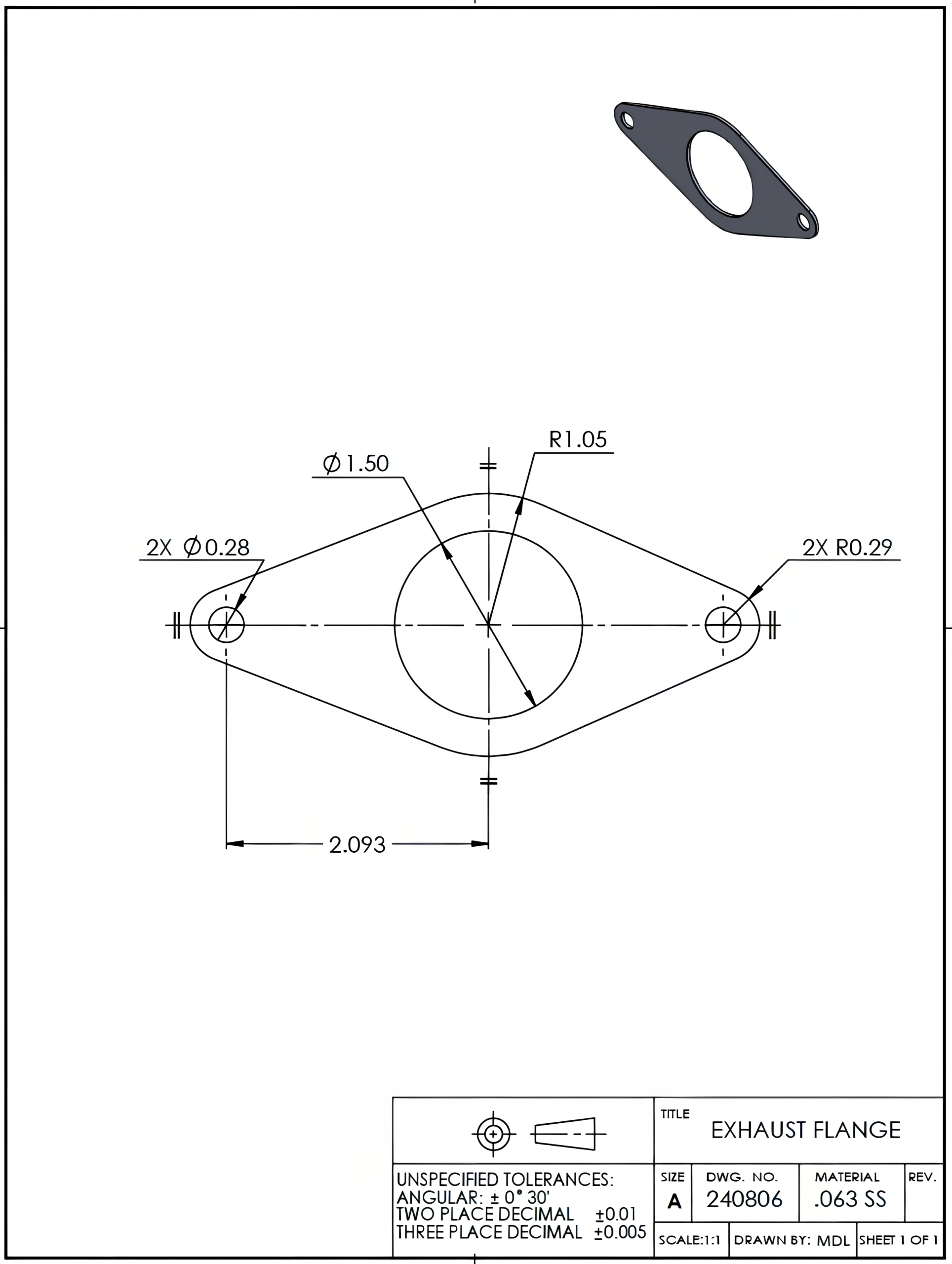
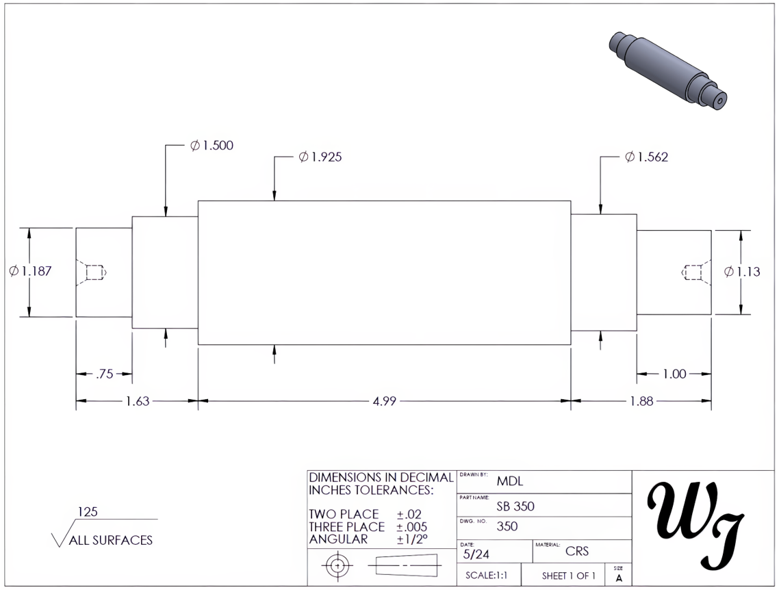
It is important to note that certain drawings may not necessitate multiple views to convey all essential information regarding the component. For instance, flat parts, such as plates or gaskets, typically require only thickness specifications. The part in Figure 6-1 only requires a single view to communicate the necessary features of the part. The thickness of the part is described in the material box as .063 SS (stainless steel). Round components may only provide a profile view and may indicate their diameter values in the same view. The circular part in Figure 6-2 uses a single view to dimension all of the part’s lengths and diameters.
6.3 Radii and Diameter Calculations
In many technical drawings featuring round or circular elements, you’ll find that dimensions are expressed using radius or diameter values. A radius is the distance from the center point to the outside of a circle or partial circle. A radius measurement is indicated by an “R” and the numerical value. A diameter is a straight-line distance across a circle that passes through the center of the circle. A diameter measurement uses the symbol “⌀” with its value. In earlier dimensioning standards, the abbreviation for diameter, “DIA,” was used to identify a dimension as a diameter value. Though the abbreviation has been replaced, it may still be seen on many drawings.
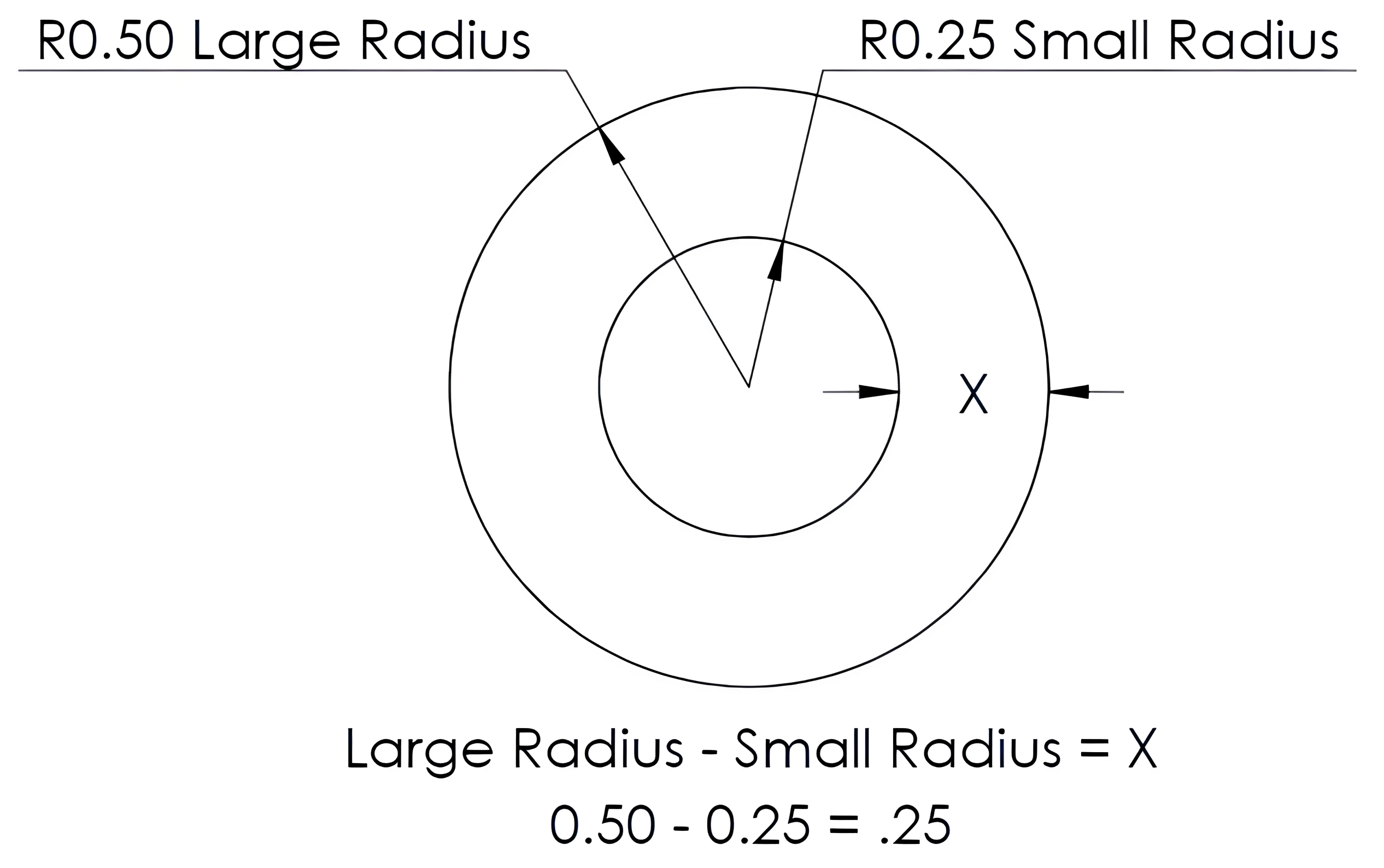
It’s common to use these radius and diameter values to determine additional dimensions. For instance, in the examples provided below, we will see how these values will be used to calculate wall thickness. To calculate for “X” in Figure 6-3, the small radius (0.25) is subtracted from the larger radius (0.50), giving a difference of 0.25 for the X value. When working with radii, you simply subtract the smaller radius from the larger one.
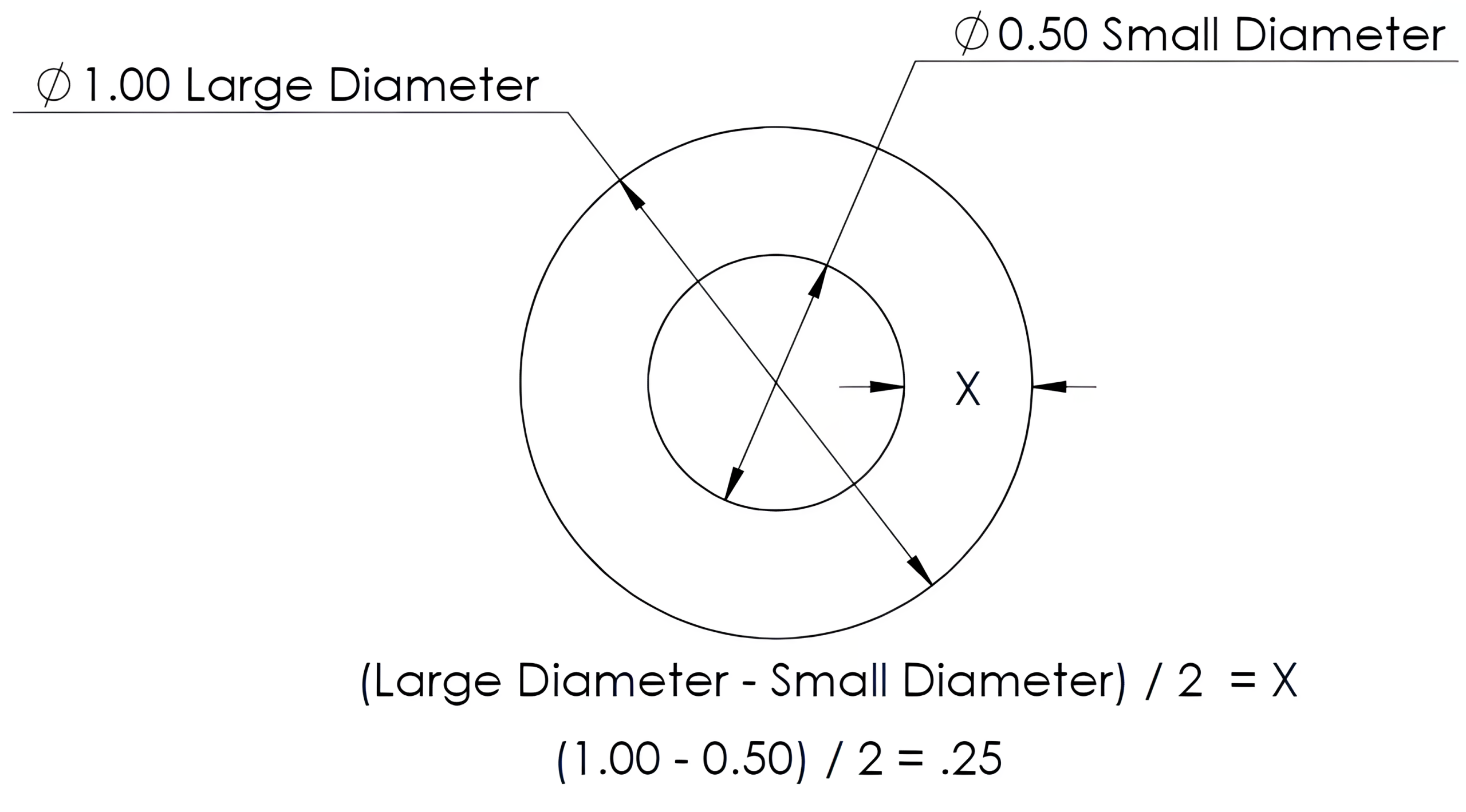
On the other hand, if you’re dealing with diameters, remember to divide your result by two after subtraction. To calculate for “X” in Figure 6-4, the small diameter (0.50) is subtracted from the larger diameter (1.00). The difference is then divided by 2, resulting in the .25 value for the X dimension.
As you progress through this material, please pay close attention to which values you use for calculations. This will ensure accuracy in your work.
6.4 Repetitive Features
Repetitive “X” Dimensions
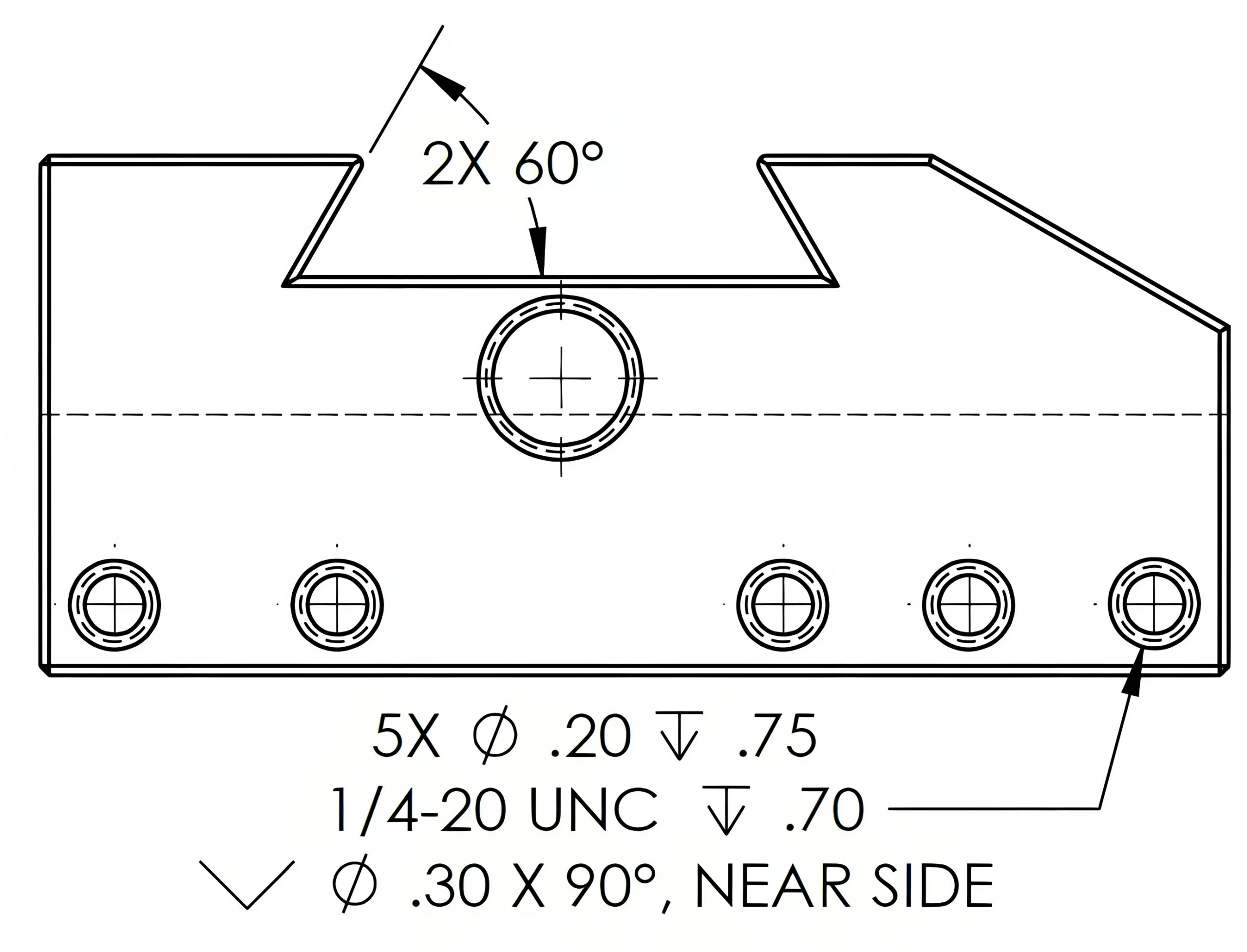
When a particular feature appears multiple times on a drawing, its details may be provided just once. The frequency of that feature will then be indicated with the letter “X” to designate “times.” Figure 6-5 uses 2X to identify the two identical angles as both 60° and 5X to identify the five smaller holes as identical.
Typical Dimensions
Typical dimensions are repetitive features identified by the abbreviation “TYP” for typical. For a location dimension, TYP can appear after a dimension to apply the same value to remaining undimensioned locations, as shown in Figure 6-6. This abbreviation is also applied to features such as radii or chamfers; all undimensioned features of similar size are intended to use the same size value as the TYP dimension.

Exercise 6.4-1
Exercise 6.4-2
Exercise 6.4-3
Exercise 6.4-4
6.5 Angular Dimensioning
Angular dimensioning is used to identify the angular size from a known reference. In most cases, the angle will be dimensioned from the vertical or horizontal surface or centerline. Angular dimensions will be expressed in degrees (°). A complete circle contains 360°. In an angular dimension, the dimension line will be curved with the curve’s center point (vertex) matching the center point of the angle. When a degree dimension is further split into a smaller portion of a degree, this may be expressed in two different ways: in degrees, minutes, and seconds; or in decimal degrees.
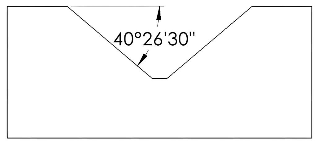
Degrees, Minutes, and Seconds (DMS) is a system for measuring angles using degrees (°), minutes (‘), and seconds (“). In this system, a degree is divided into 60 minutes, and each minute is divided into 60 seconds. The format for expressing DMS is degrees° minutes’ seconds”. For example, the angle could be expressed as 40° 26′ 30″ or 40 degrees, 26 minutes, and 30 seconds. See Figure 6-7.
Decimal degrees is a system for measuring angles or coordinates using decimal fractions of a degree. The formula displays how the conversion is made. To convert minutes, you take the number of minutes and divide it by 60 (because there are 60 minutes in a degree). For seconds, you divide the number of seconds by 3,600 (60 seconds x 60 minutes = 3,600 seconds within a degree). After that, you simply add both results together to get your decimal value.
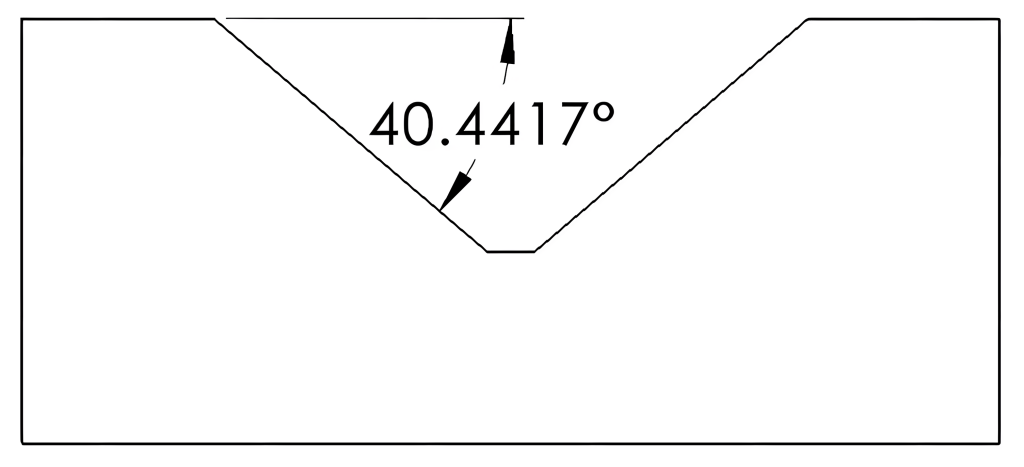
For example, let’s say we have an angle of 40° 26′ 30″. You would calculate it as follows: Take the minutes (26) and divide that by 60 to get approximately .433. Then, for the seconds (30), divide that by 3,600, resulting in about .0083.
40° + .433 + .0083
The resulting decimal degree angle is 40.4417°. View Figure 6-8.
Both DMS and decimal degrees are used in industrial prints to accurately communicate angular dimensions. The choice between the two formats may depend on the designer’s preference or a company’s standard practice. DMS may have the advantages of being a more familiar format for many professionals and correlating the format of many angle measuring instruments. The decimal degree format has the advantage of using one singular continuous number, simplifying the process of performing angular calculations.
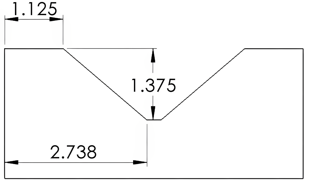
Linear dimensions indicate the size or distance between two points. These are often used to provide the endpoints of the angle rather than providing the angle value. This technique, which gives the coordinate locations of the angle endpoints, may be preferred by many designers because it can provide better control over the two endpoints of the angle. Figure 6-9 depicts linear dimensions.
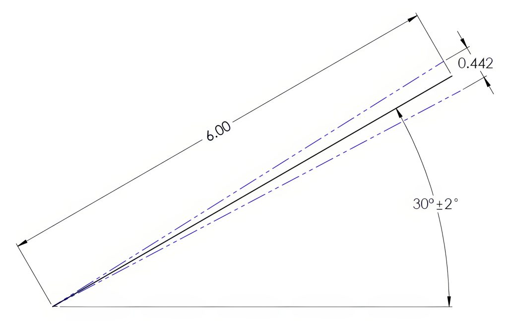
When an angular dimension is assigned a size tolerance, the distance of the variation increases as the distance from the vertex increases; Figure 6-10 illustrates this concept. In this example, the allowable variation in angle is illustrated with the blue phantom lines. An angle dimension allowing a variance of ±2° could have an endpoint location variance of 0.442″ over a distance of 6.00″.
Angular Calculations
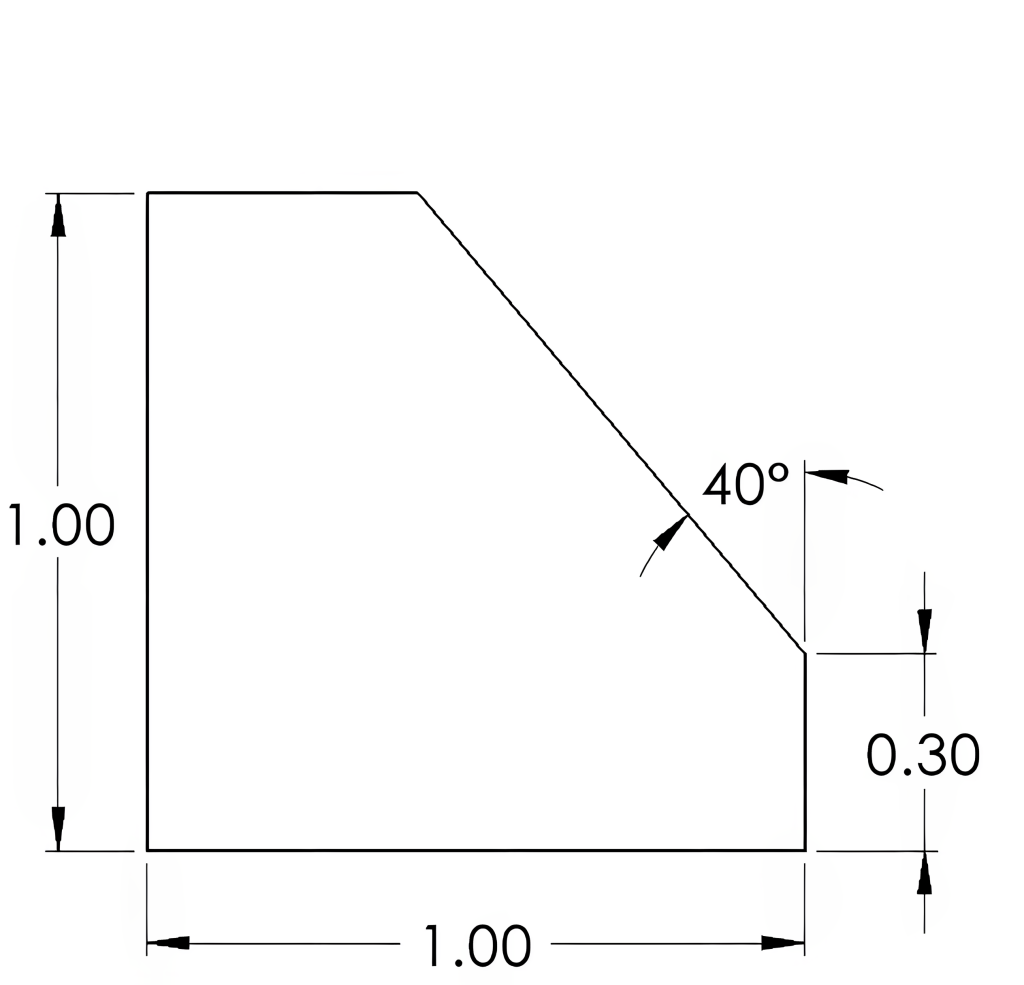
Whether angular or coordinate dimensioning is used for angles, this information can be used for calculations of lengths and missing angles in part drawings. Knowing some information about triangles, particularly right triangles, will aid in many angular calculations. All triangles will contain three angles with a sum equal to 180°. Triangles containing one angle of 90°, known as right triangles, will leave the sum of the two remaining angles equal to 90°. In Figure 6-11, for example, the angle of 40°, along with the linear dimensions, can be used to calculate the remaining dimensions.
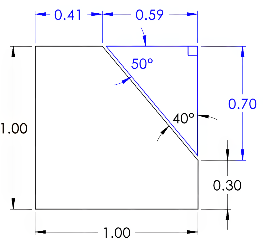
In Figure 6-12, you can see how a right triangle can be used to identify the 50° angle. The triangle drawn in Figure 6-13 contains a 90° angle, identified by the square in the corner, leaving 90° between the remaining two angles. With 40° being dimensioned, 50° remains for the third angle. In the example, 0.70 is obtained by subtracting 0.30 from the height of 1.00. The values of 0.41 and 0.59 will require the use of trigonometric calculations involving right triangles to determine.
6.5 Included Angles
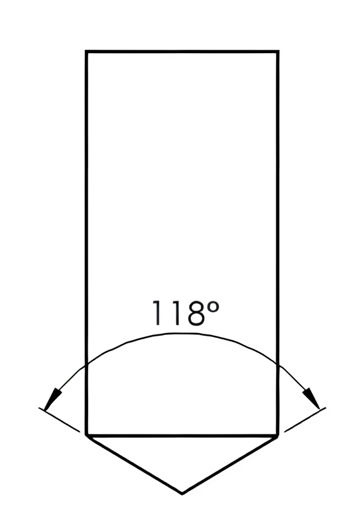
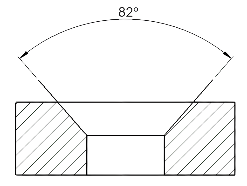
An included angle is the angle between two sides of a triangle or two lines that intersect at a point. It is the angle formed by the two sides or lines when they meet at a common vertex. The included angle will be less than 180°. Some common examples are the angles of drill points shown in Figure 6-13 and countersinks in Figure 6-14.
 |
 |
|---|
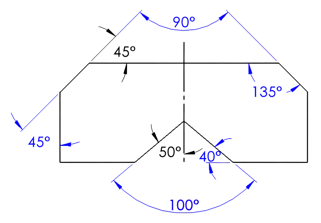
In Figure 6-15 the included angles of 90° and 100° are calculated from the given angles of 45° and 50°. The centerline indicates the part is symmetrical, making the angle opposite the 45° also 45°. Extending these lines to where they meet will create a triangle. Subtracting the two 45° corners from 180° will leave the 90°. The 50° angle can be doubled to obtain the 100° angle. A straight line of 180° minus the 45° will leave 135°. The 50° angle can be used to create a right triangle to determine the 40° angle.
6.6 Bolt Circles
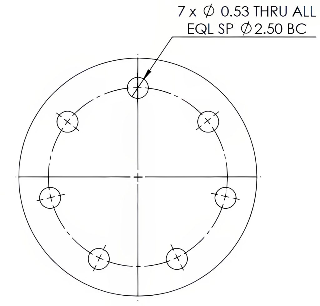
Bolt circles, commonly found in circular parts, are a series of clearance holes or threaded holes designed for fastening. These patterns consist of three or more holes arranged around a shared center point, making them concentric. The center line of this hole pattern represents the bolt circle itself, which is dimensioned using either a leader line with the bolt circle (BC) diameter following the hole information or a diameter dimension line.
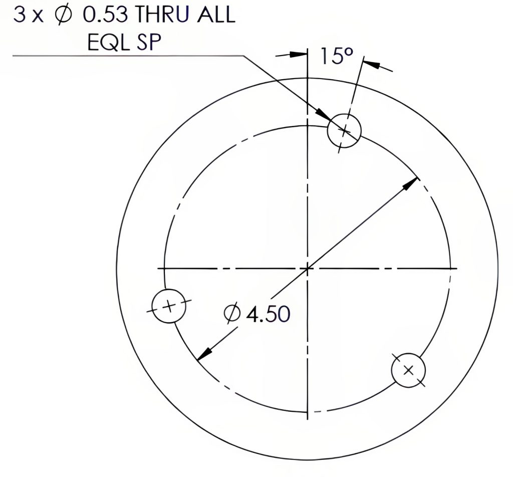
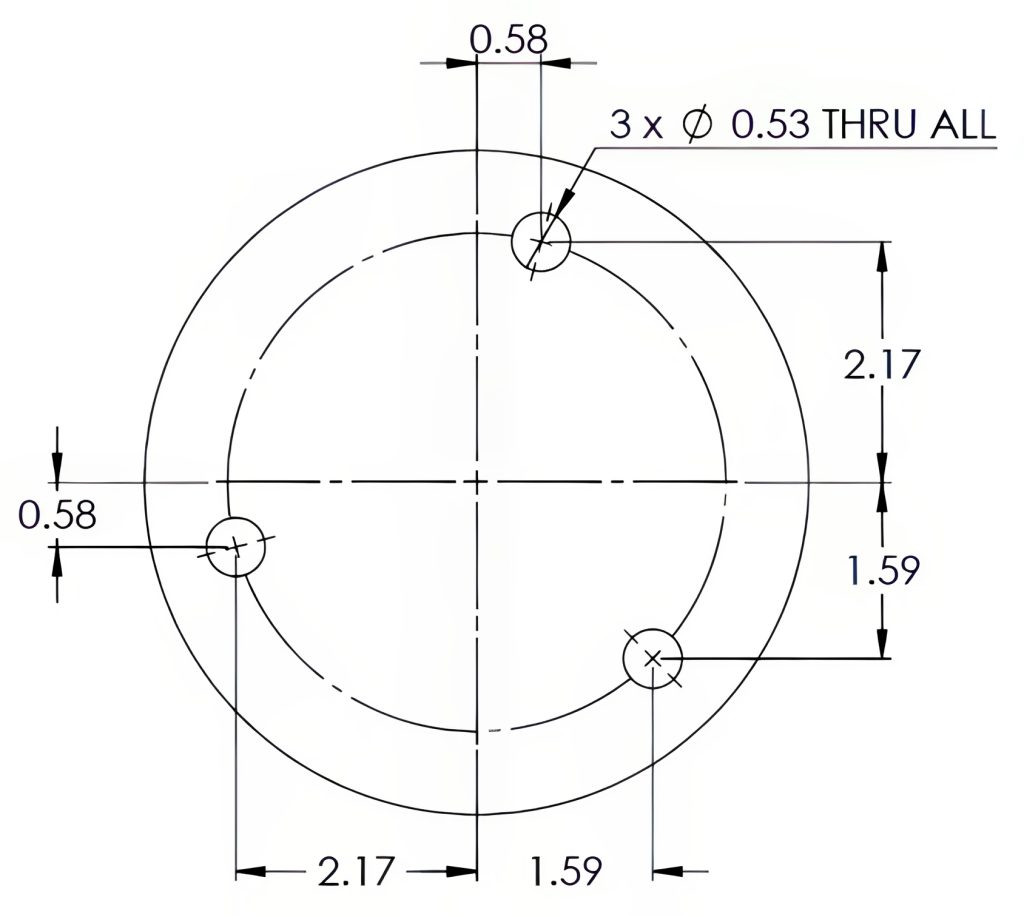
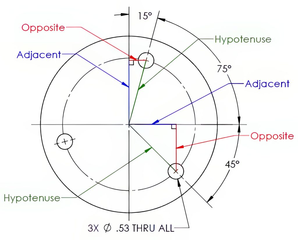
When it comes to the placement of these holes, there are two common methods for dimensioning: their positions can be referenced using coordinate locations, or angular dimensions based on vertical or horizontal centerlines. The holes are often equally spaced, abbreviated “EQL SP,” with at least one hole aligned along the vertical or horizontal axis, as in Figure 6-16, or measured angularly from the vertical or horizontal axis, as in Figure 6-17. If you’re calculating angles between equally spaced holes, you can simply divide 360° by the total number of holes involved.
 |
 |
|---|
Coordinate dimensioning of the locations dimensioned from the vertical and horizontal centerlines is commonly used in milling machines for locating the X and Y axis locations. This style of bolt circle dimensioning can be most relevant to the reader but may create congestion in the drawing. See Figure 6-18. The coordinate locations may also be calculated using right triangle trigonometry functions, the known angle, and hypotenuse length (the bolt circle radius) as shown in Figure 6-19. Many CNC machines, programming software, and even digital readouts are capable of calculating these positions as well.
 |
 |
|---|
Learning Activities
Exercise 6.5-1
Exercise 6.5-2
Exercise 6.6-1
Exercise 6.6-2
References:
Barsamian, M. A., & Gizelbach, R. (2022). Machine trades print reading. Goodheart-Willcox.
Schultz, R. L., & Smith, L. L. (2012). Blueprint reading for machine trades (7th ed.). Pearson.
Images:
All images by Mark Lorier and licensed under CC BY-NC 4.0 except where otherwise noted.

