5. Dimensioning Systems
5.1 Introduction
Learning Objectives
- Describe methods of dimensioning drawings
- Relate dimensioning systems to mathematical concepts
- Explain how baselines are used for locating a part for manufacture
- Explain how coordinate dimensioning is used in CNC machining
- Convert dimensions to other units
- Demonstrate the rules of dimensioning a part
- Calculate the dimensions on a print
Terms
- Dimension
- Tolerance
- Datum
- Datum dimensioning
- Arrowless dimensioning
- Chain dimensioning
- Broken-chain dimensioning
- Tabular dimensioning
- Cartesian coordinate
- Absolute zero
- Decimal inch dimension
- Fractional dimensioning
- Nominal size
- Metric dimensioning
- Dual dimensioning
A dimension refers to the specific measurements that define the size, shape, and location of features on a drawing, such as the size and location of holes on a part. These dimensions are essential for accurately interpreting and constructing the design as intended. One key aspect of reading and interpreting technical drawings is interpreting the dimensioning system. This involves assigning numerical values to various dimensions to ensure the final product meets the desired specifications. This chapter will explore the different methods of dimensioning features and the dimensioning techniques that are used.
5.2 Dimensioning Techniques
When we start to explore drawing dimensions, it is essential to grasp some fundamental dimensioning rules and best practices that drafters should follow. Having a basic understanding of these practices will help you gain a better understanding of the drafter’s intentions and will assist you in locating the required sizes.
In any detailed drawing, all required dimensions that fully define the part must be present. The printed design should not need to be measured or “scaled.” If you, as the print reader, find that a drawing has incomplete or unclear information, seek clarification from the draftsperson or others involved in the design. Assumptions should be avoided.
Additionally, when the drawings, lines, and features are visually aligned or appear perpendicular, they will be in line unless stated otherwise. Lastly, the positioning of a feature’s dimensions should be placed on the view in which its profile is most clearly visible. Dimensioning to hidden lines is to be avoided when possible.
A print can be dimensioned in a variety of ways to control the functional sizes of the features and overall size. While all the design’s size information should be present on the drawing, all size information must only be presented once to avoid confusion with the tolerance or allowable size variation of a dimension; this is further covered in Chapter 8. Because of this, some feature sizes must be calculated from other dimensions.
Datum Dimensioning
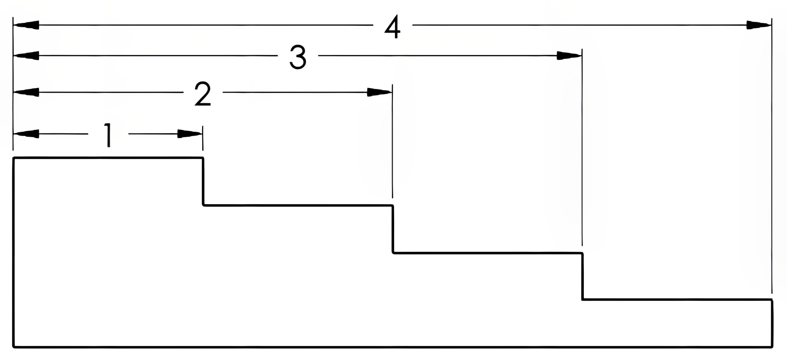
A datum represents a precise theoretical location, like the edge of a part or the center of a hole, that serves as a reference baseline for measurements. Datum locations are typically chosen by the drafter to best control the function of the part and often to control the relationship between mating parts within an assembly. This datum should provide a consistent reference for part sizes and feature locations. Datum dimensioning (also referred to as baseline dimensioning) provides the dimensions or distances from features back to the datum. Figure 5-1 uses datum dimensioning to locate each of the four steps on this part. Each step is referenced from the same left edge of the part using extension and dimension lines. Finding the lengths of the second, third, and fourth steps would each require calculating the difference between two dimensions.
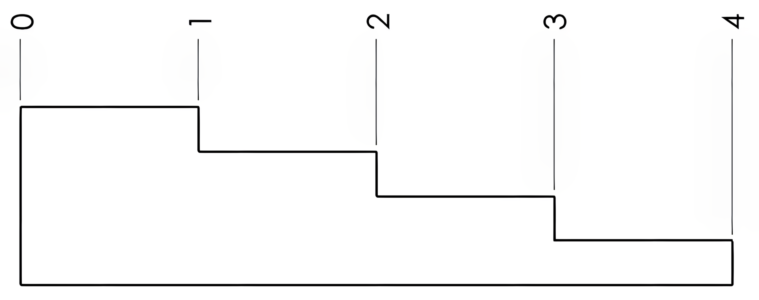
Another style of datum dimensioning that leaves out the dimension lines is known as arrowless dimensioning. This style of dimensioning omits these extra lines to help minimize clutter on the print, as shown in Figure 5-2. This style uses only the extension line ending with the dimension presented perpendicular to the line. In arrowless dimensioning, the dimensions will maintain vertical or horizontal alignment with each other. Often these dimensions may be too close to maintain a straight extension line without the dimension values overlapping each other. In this case, the extension line will “bend” outside of the part drawing, as observed in Exercise 5.2-2 near the end of this chapter. Arrowless dimensioning is often used for parts to be manufactured using computer numerical control (CNC) machining processes due to its common reference location and cleaner layout, reducing the difficulty in identifying the correct dimension.
Chain Dimensioning
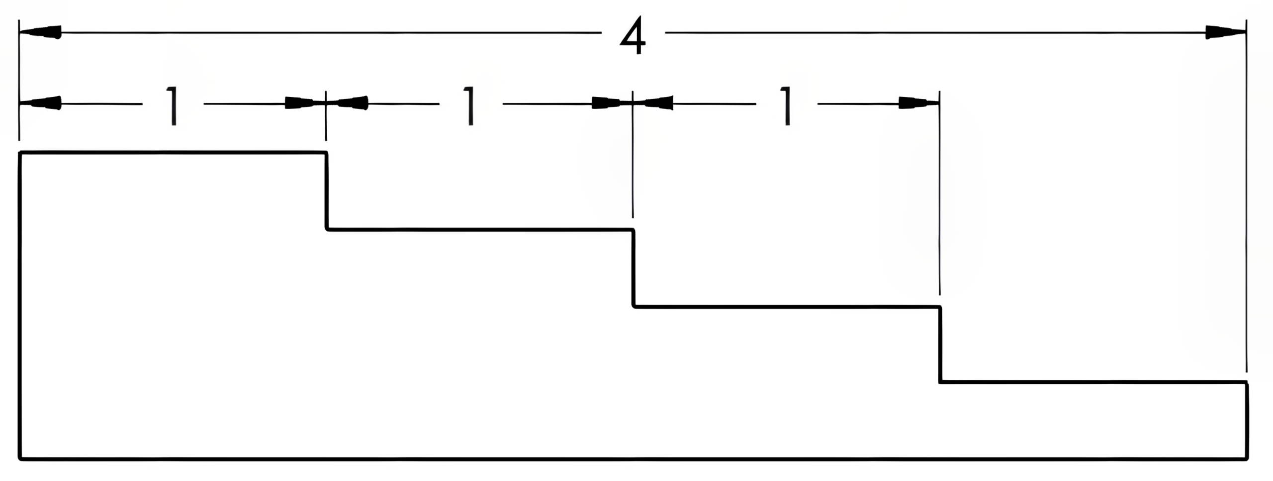
Chain dimensioning style involves dimensioning from one feature to another. Rather than locating from one consistent datum, the second feature is referenced from the first, the third referenced from the second, and continuing with any number of features being located from the previous one. Finding the lengths from the end to the second and third steps, as well as the overall length, requires adding the dimensions of each included step. See Figure 5-3 for an illustration of chain dimensioning.

Broken-chain Dimensioning
The broken-chain dimensioning method omits one chain but includes the overall length. The three steps are subtracted from the overall length to find the missing length, as shown in Figure 5-4.
Tabular Dimensioning
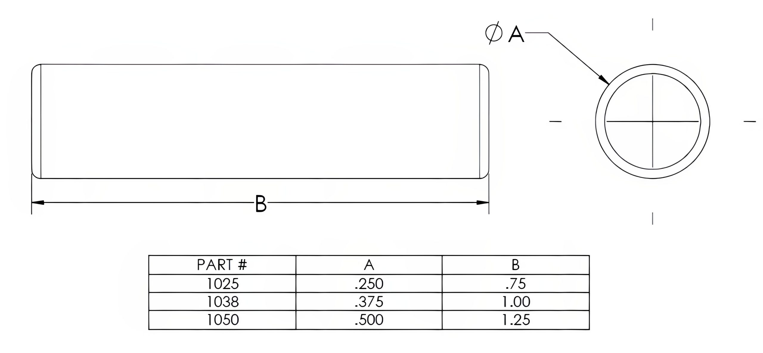
Tabular dimensioning is a system in which letters and/or numbers are used to identify a feature size or location, which is referenced to a table containing the coordinating size dimensions. This system of dimensioning is commonly used when the shape of a part is consistent, but the size dimension may vary among different parts. Some examples of this tabular style may be a bolt or a pin, as shown in Figure 5-5.
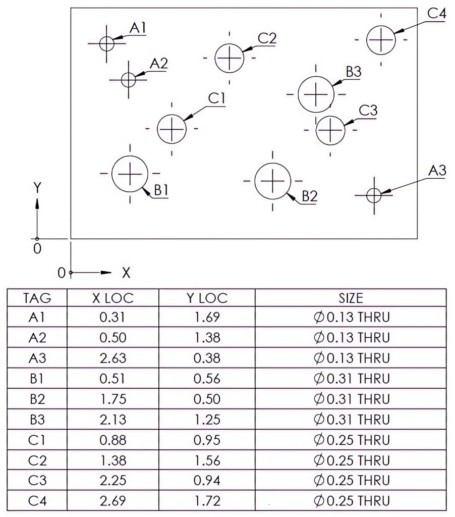
Another opportunity for the use of tabular dimensioning may occur on a drawing containing a large number of similar features, such as a part containing multiple hole locations. Tabular dimensioning, also referred to as a hole table, in this case, will prevent having an excessive amount of dimension and extension lines, creating a difficult-to-read drawing. The table row will contain an identifying letter and/or number label to correspond with the label or “tag” on the part feature. In Figure 5-6, the hole positions are measured from a specified origin datum and given in X and Y coordinate locations in the table, along with the hole size.
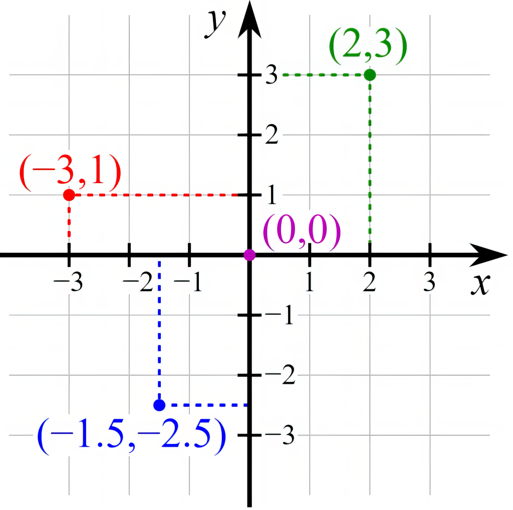
The X and Y coordinate positions are known as a Cartesian coordinate system. A Cartesian coordinate system (also called a rectangular coordinate system) is an ordered pair of perpendicular lines (axes) using the same unit of length for each axis. The intersection where the axes meet is the origin (0, 0) for each line. In most Cartesian coordinate illustrations, as well as a typical milling machine application, the horizontal line is referred to as the X-axis, and the vertical, as shown two-dimensionally, is referred to as the Y-axis. All X values to the right of the origin are positive; the left values are negative. All Y values above the origin are positive, and values below the origin will be negative. Each coordinate location is identified by its X location first and then its Y location (X, Y). The four points in Figure 5-7 are marked and labeled with their coordinates: (2, 3) in green, (−3, 1) in red, (−1.5, −2.5) in blue, and the origin (0, 0) in purple. This dimensioning style is often used for drawings to be machined on CNC milling machines, with the same datum used on the drawing being used as the absolute zero location of the part in the machine and using the X and Y locations to create a program for manufacturing the part. Absolute zero location means that the location values will always be referenced from this location.
5.3 Dimension Units
There are two primary measurement units commonly used for dimensioning prints. Both imperial (inch) and metric units are frequently used for dimensioning purposes. Inch dimensions, also known as US customary units, are widely adopted across numerous industries and companies within the United States and Canada. In most other countries, metric values represent the standard measurements. Metric values will also appear on US drawings for products intended for international use.
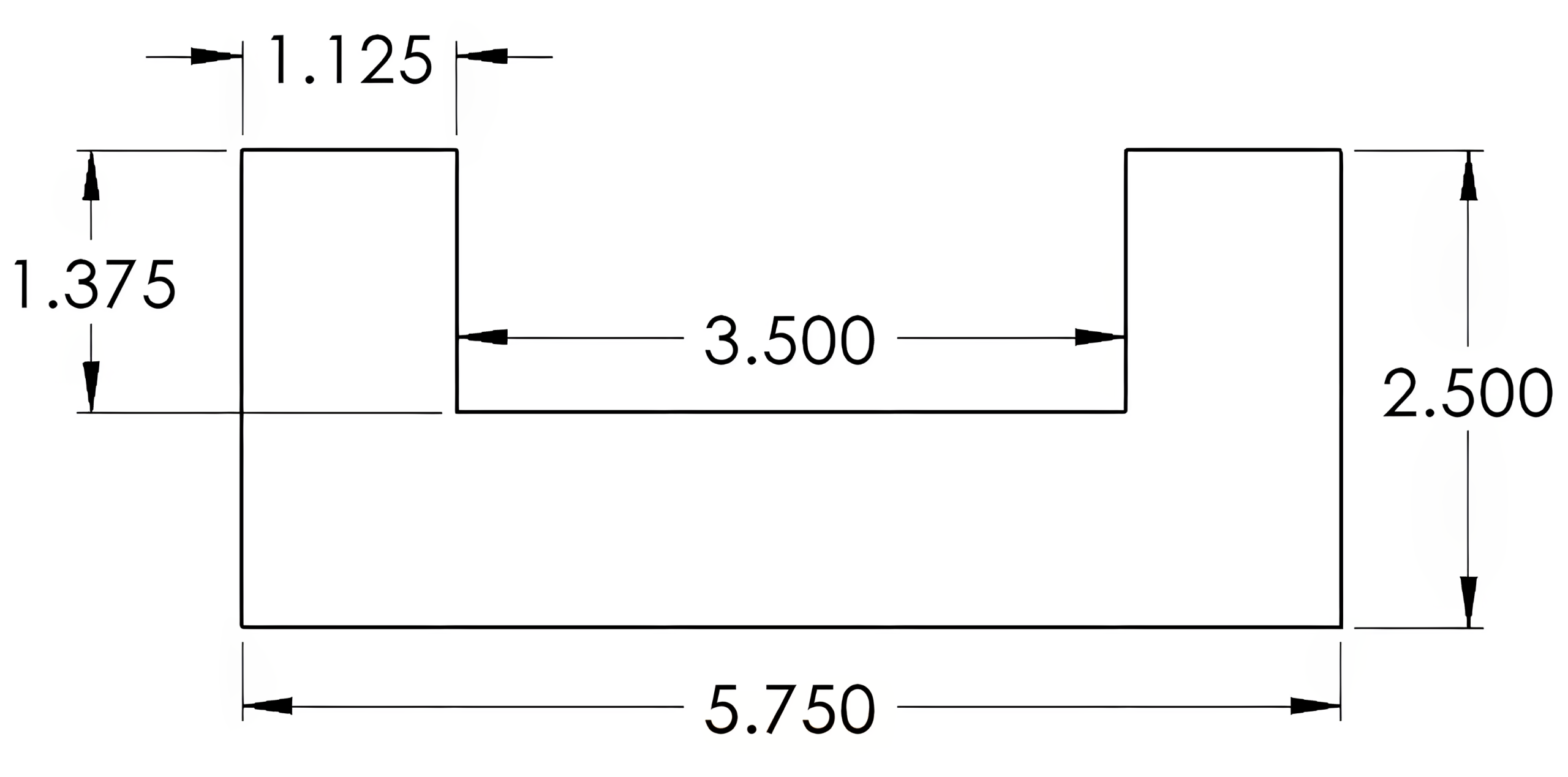
Decimal inch dimensions are based on decimal inches. A decimal inch is a fraction or portion of an inch expressed in decimal form. These are the most commonly used dimension units in the United States. These units are expressed in tenths (.1 = 1/10), hundredths (.01 = 1/100), thousandths (.001 = 1/1000), and ten thousandths (.0001 = 1/10,000) of an inch. Decimal inch values allow for simplified calculations and an increased accuracy over fractional dimensions. The number of decimal places expressed on the print will determine the accuracy required; see Figure 5-8. This concept will be further explained in Chapter 8.
When discussing decimal inch values in a manufacturing setting, the tenths (.1) and hundredths (.01) values are not expressed as they would be in other settings. The values will be expressed in thousandths of an inch regardless of the number of decimal places used. For example, a value of .25 will be expressed as “two-hundred and fifty thousandths” and not “twenty-five hundredths.” When a fourth decimal place (ten-thousandths value) is expressed, the last number is added to the expression. A value of .0625 would be “sixty-two thousandths and five-ten-thousandths” or simplified to “sixty-two and five-tenths.”
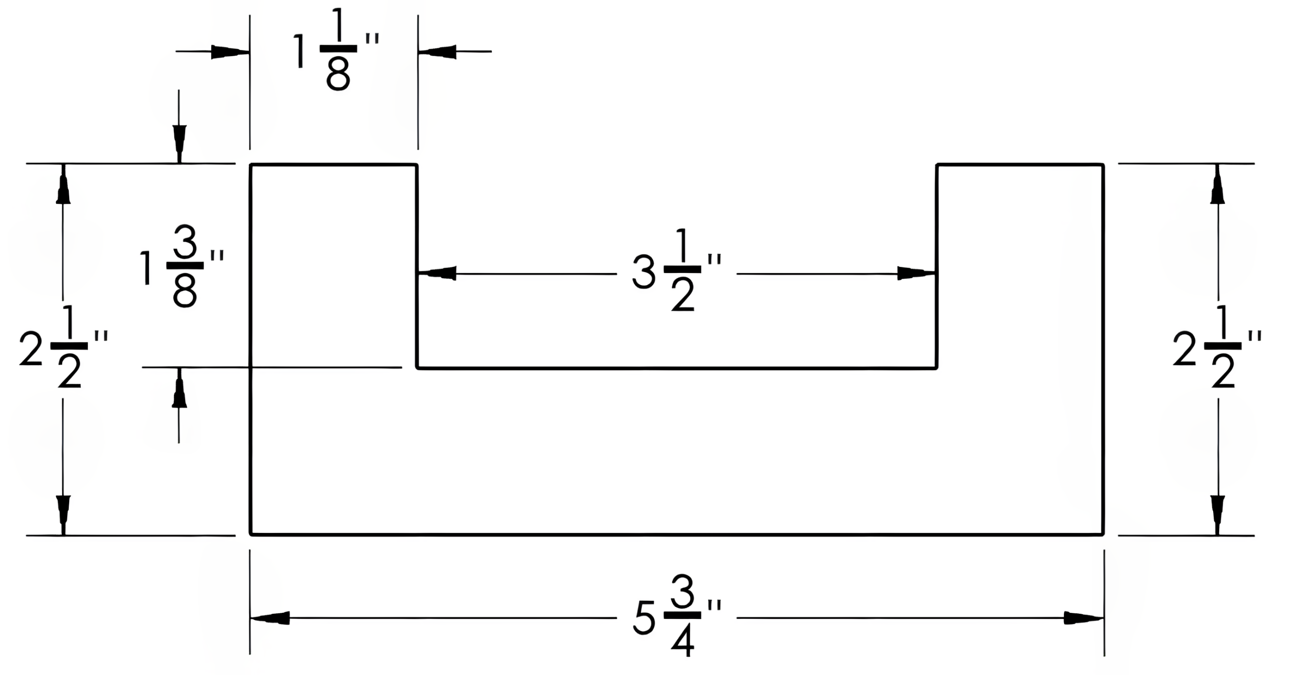
Fractional inch dimensions are usually measured/represented in values of 1/2 (halves), 1/4 (quarters), 1/8 (eights), 1/16 (sixteenths), 1/32 (thirty-seconds), and 1/64 (sixty-fourths). This dimensioning style may be found on drawings with more generous tolerances such as a casting or a welded fabrication print. Fractional sizes are often used when displaying the material’s stock size or a feature’s nominal fraction size. A nominal size refers to a general dimension used for identification and communication purposes, but it does not necessarily reflect the actual physical measurement of the part or feature. One example would be a 1/2-13 bolt, with 1/2″ as the nominal outside diameter. However, the actual diameter may vary from .4822″ to .500″. Another commonly used example is in dimensional lumber, where the finished measured size of a 2″x4″ is actually 1 1/2″ x 3 1/2″. See Figure 5-9.
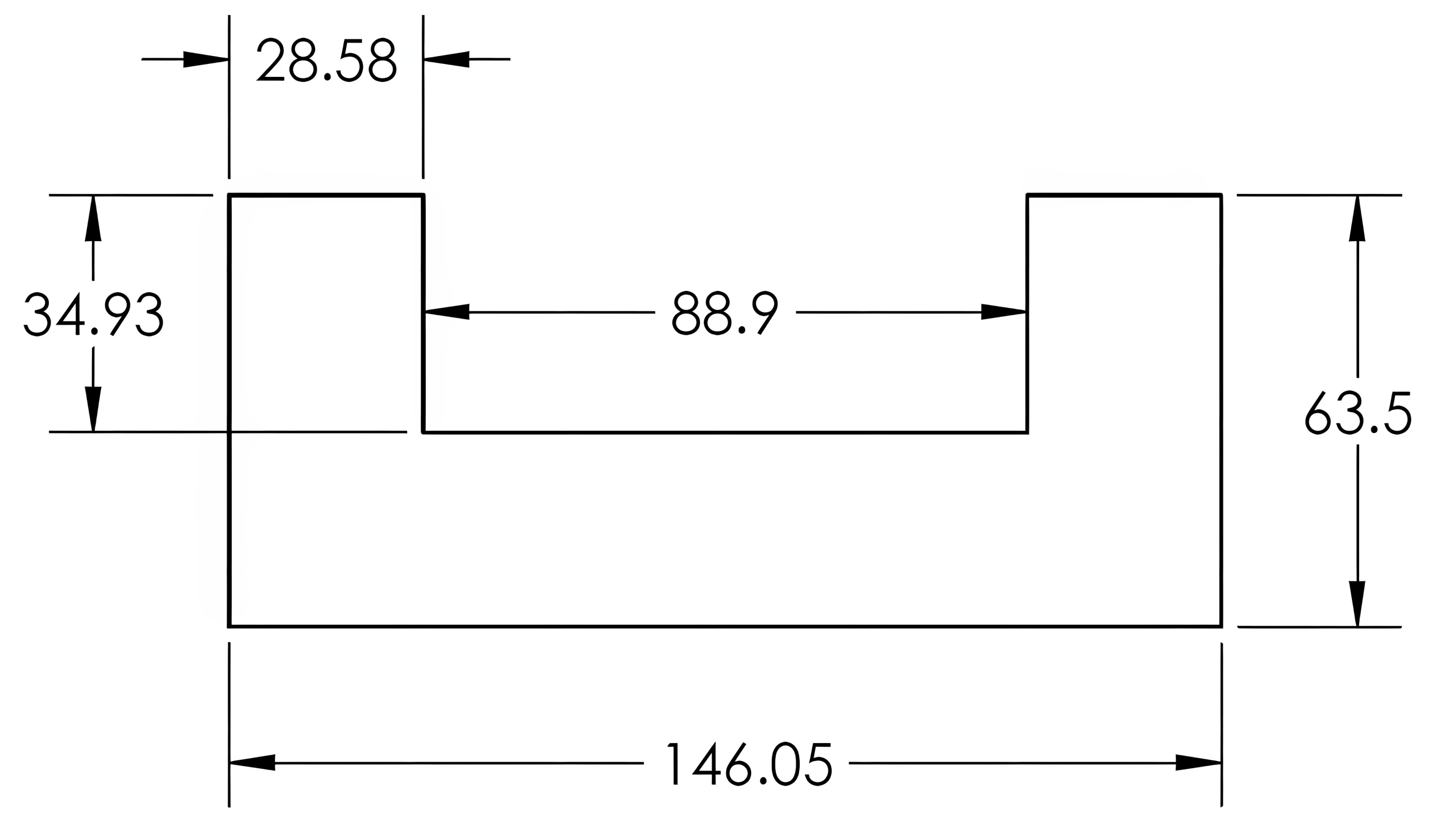
Metric dimensioning is commonly used in many industrial prints, known as the International System of Units, abbreviated “SI” from its French translation. The meter is the base unit of the metric system, with the millimeter (mm) being the most common metric unit for drawings, as depicted in Figure 5-10. Depending on your environment, equipment, and measuring tools available, a drawing using metric units may require the reader to convert the units into decimal inch equivalents. This can be done by using the ratio of 1 inch equaling 25.4 millimeters.
To convert an inch value to metric, multiply the value by 25.4 (inch value x 25.4 = mm).
Example: 3.5 inches x 25.4 = 88.9 mm
To convert from millimeters to its inch equivalent, divide by 25.4 (metric value / 25.4 = inch).
Example: 146.05 mm ÷ 25.4 = 5.750 inches
The number .03937 may be used in place of 25.4, with the formulas reversed: inch value / .03937 = mm and a metric value x .03937 = inch.
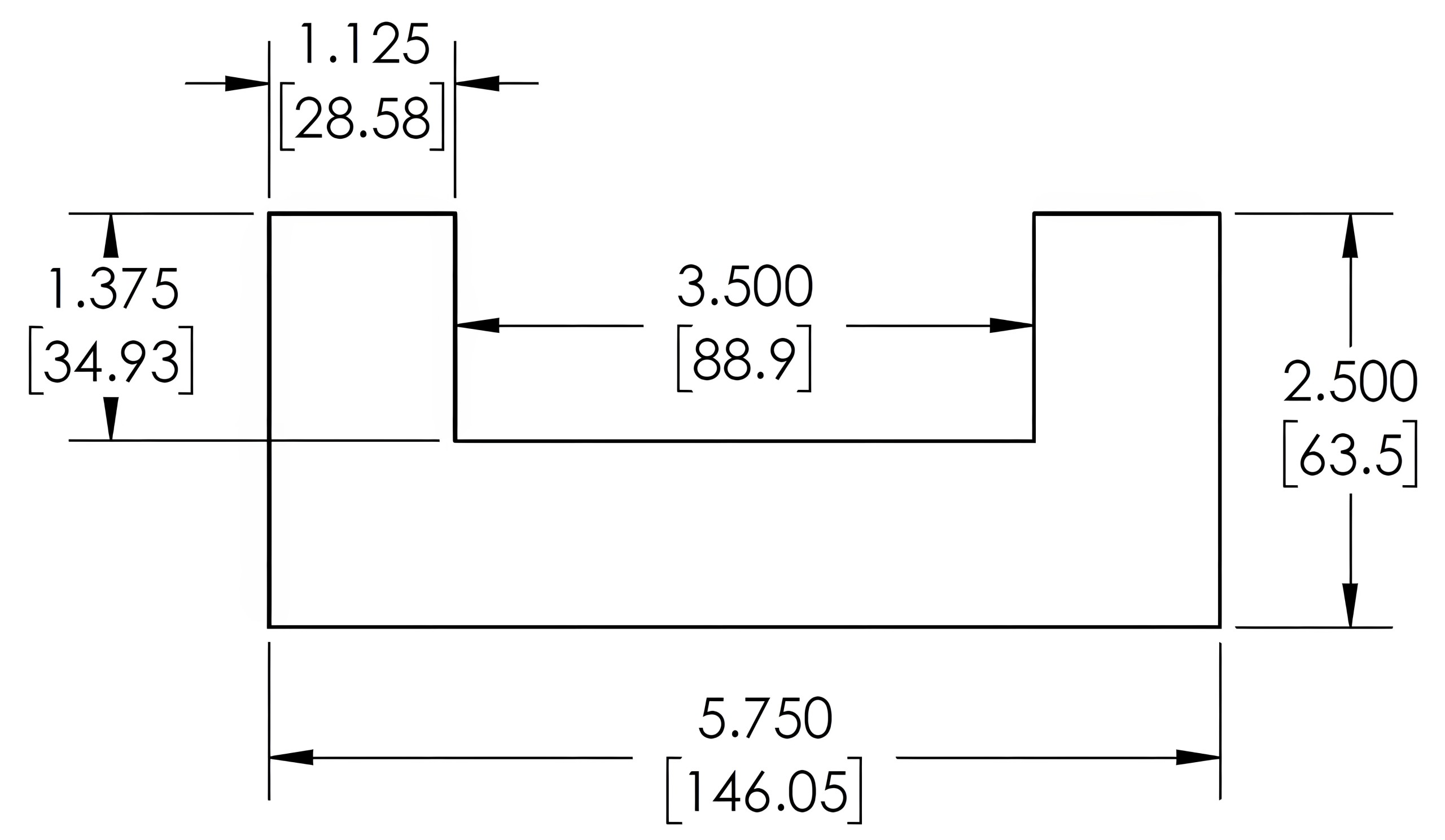
Dual dimensioning is a system that displays both inch and metric values together. In dual dimensioning, the original system used is displayed along with the alternate system shown in brackets [ ]. The manufacturing company’s preferred unit measurement may not be the same as every print reader involved in the process of the final part. Dual dimensioning eliminates the need to calculate the conversion of each dimension. View Figure 5-11.
Learning Activities
Exercise 5.2-1
Exercise 5.2-2
Exercise 5.3-1
Exercise 5.3-2
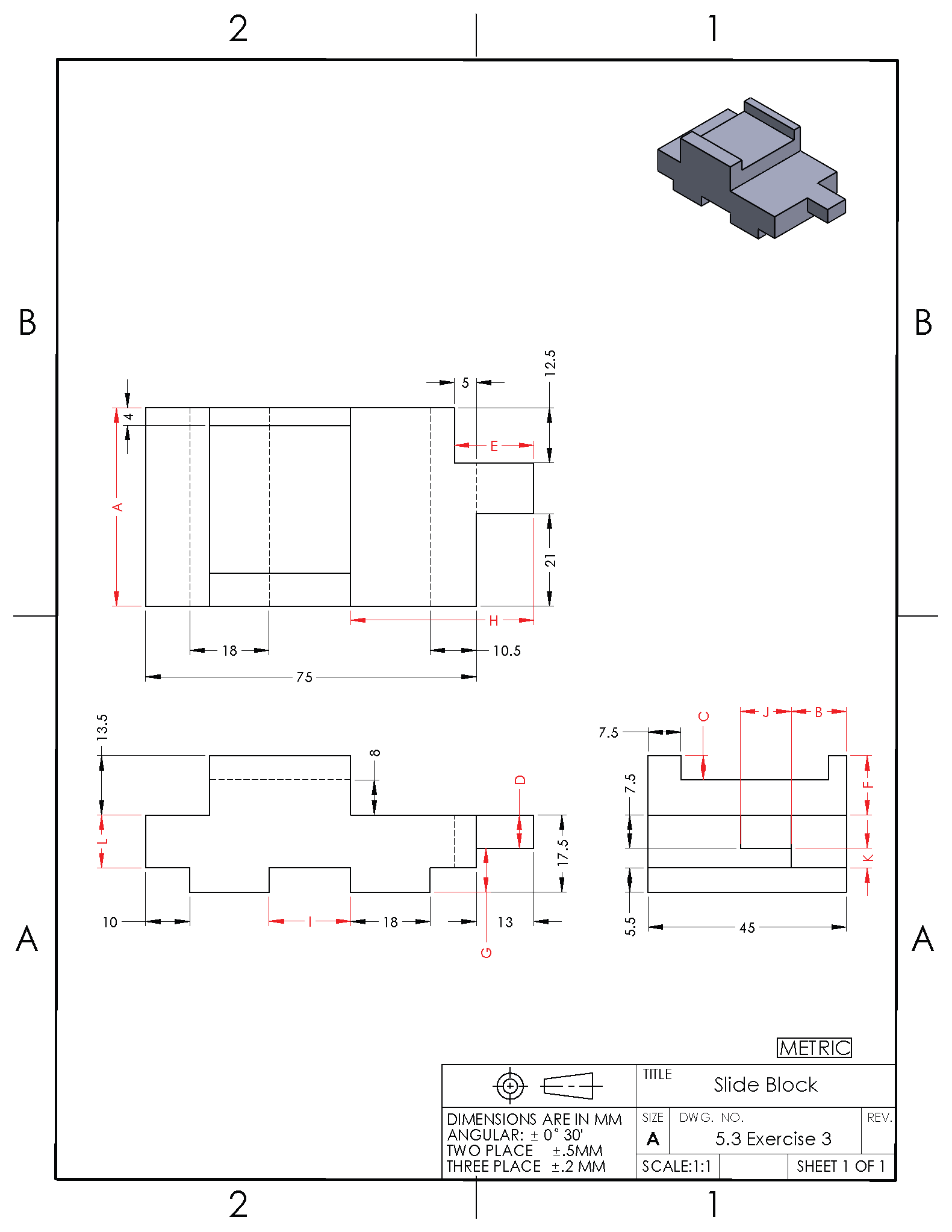
Directions: Click and drag each dimension to the corresponding letter in the print below.
Exercise 5.3-3
Directions: Click the image to open it in a new tab. Reference the image to answer the following questions.
References:
Barsamian, M. A., & Gizelbach, R. (2022). Machine trades print reading. Goodheart-Willcox.
Schultz, R. L., & Smith, L. L. (2012). Blueprint reading for machine trades (7th ed.). Pearson.
Images:
All images by Mark Lorier and licensed under CC BY-NC 4.0 except where otherwise noted.

