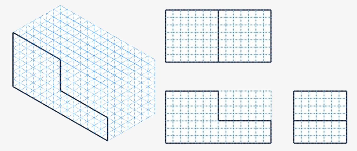
4. Objects in Different Views
4.1 Introduction
Learning Objectives
- Identify correct views for objects
- Visualize how actual part features should appear based on print features
- Sketch drawings incorporating the alphabet of lines
- Sketch simple orthographic drawings
- Draw missing views of objects based on given views
Terms
- Isometric view
- Orthographic view
- Dimetric view
- Trimetric view
In this chapter, we will identify the correct views of objects by use of visible and hidden lines. We will also explore the art of sketching objects using both orthographic and isometric techniques. Sketching is a fundamental skill for designers, engineers, and hobbyists, as it allows them to quickly convey their ideas and designs on paper. By mastering both orthographic and isometric sketching, you will be able to accurately capture the dimensions and details of any object. Throughout this chapter, we will look into the principles of sketching, practice different techniques, and develop the ability to sketch in both styles, as well as give you a greater understanding of these views as you work with them.
4.2 View Identification
The ability to visualize how an actual part should appear based on print features is crucial in print reading. This skill ensures that the interpretation of technical drawings translates accurately into physical components, reducing errors and improving efficiency in manufacturing. Isometric views provide a three-dimensional representation of an object. This view helps in understanding the overall shape and structure of the part. On the other hand, orthographic views offer a series of two-dimensional projections of the object, typically including the front, top, and side views. These projections are essential for detailing the exact dimensions and relationships between different features of the part. Mastering both isometric and orthographic views allows for a comprehensive understanding of blueprints, ensuring precise and effective communication of design intent.
Complete the exercises below to enhance your skill in imagining the physical forms of each section as you complete the missing views. Apply what you’ve learned about projection views, along with visible and hidden lines.
View Identification Exercise 1
View Identification Exercise 2
4.3 Sketching Orthographic Views
Whether you’re producing part prints for manufacturing or need to quickly convey the specifics of a three-dimensional item on a two-dimensional sheet, mastering orthographic drawings is essential for ensuring a clear grasp of the object’s form, size, and characteristics. Enhancing this skill will not only improve your capability to communicate design concepts to others without relying on CAD software, but also improve your ability to visualize and perceive three-dimensional shapes from an orthographic perspective.
The following YouTube video will illustrate the isometric view of Orthographic Sketch 1 transferred into a three-view orthographic sketch.
Orthographic Sketching Exercises
Use grid paper to complete the missing views to each orthographic sketch. Include any visible and hidden lines. (Solutions are provided in the Learning Activities – Solutions section.)
Orthographic Sketching Exercises
Orthographic Sketch 1
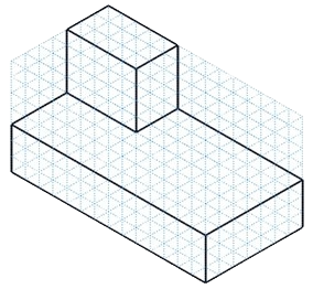
Orthographic Sketch 2
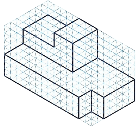
Orthographic Sketch 3
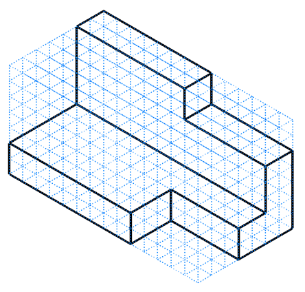
Orthographic Sketch 4
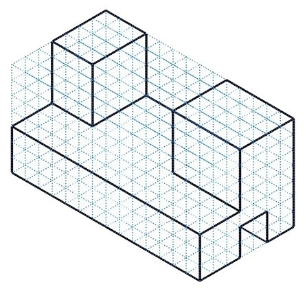
Orthographic Sketch 5
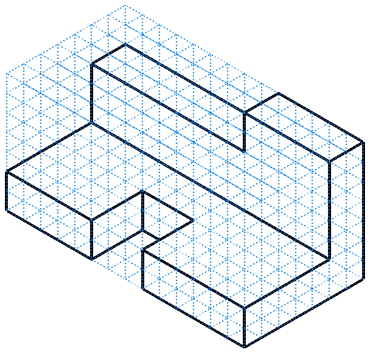
Orthographic Sketch 6
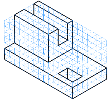
4.4 Sketching Isometric Views
While an orthographic sketch can help communicate an object’s details and dimensions, an isometric drawing provides a clear and comprehensive way to visualize a three-dimensional object on a two-dimensional surface. The ability to represent an object three-dimensionally by creating an isometric sketch from orthographic views will also enhance one’s ability to visualize complex multi-view drawings quickly.
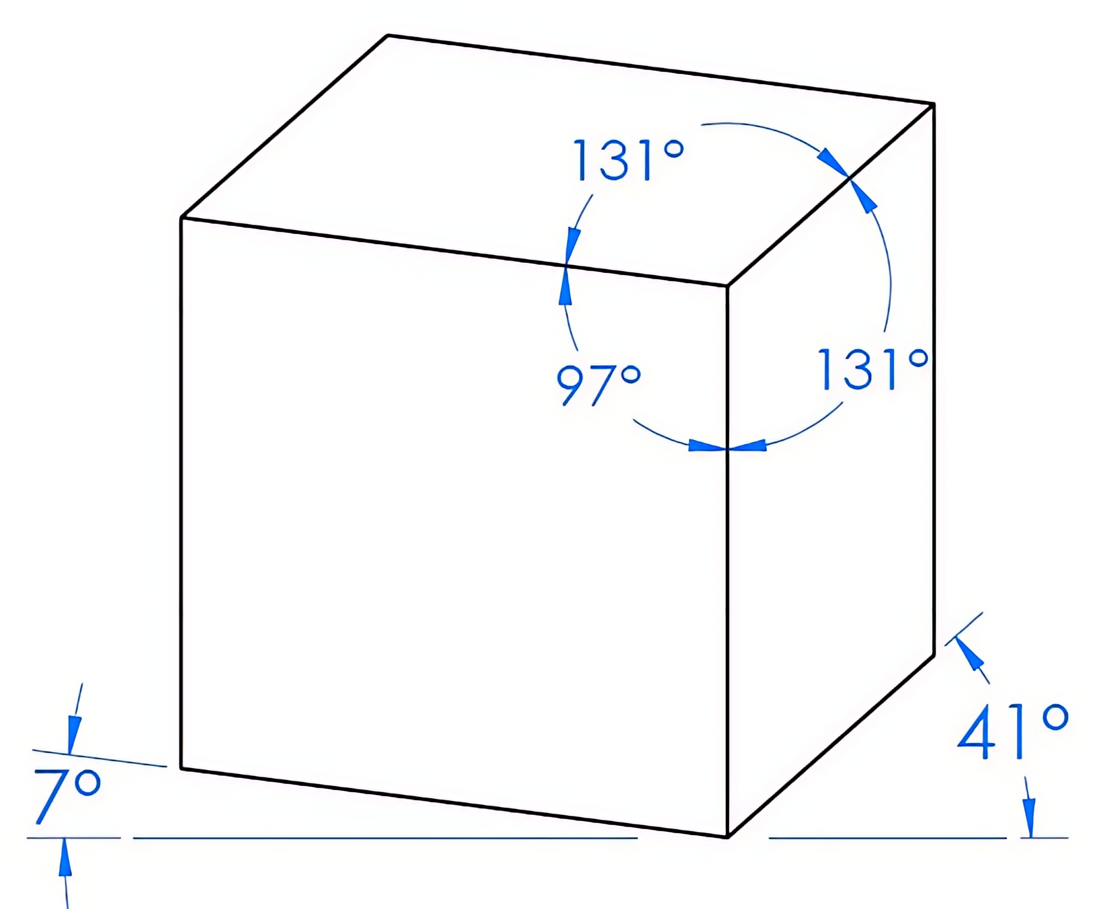
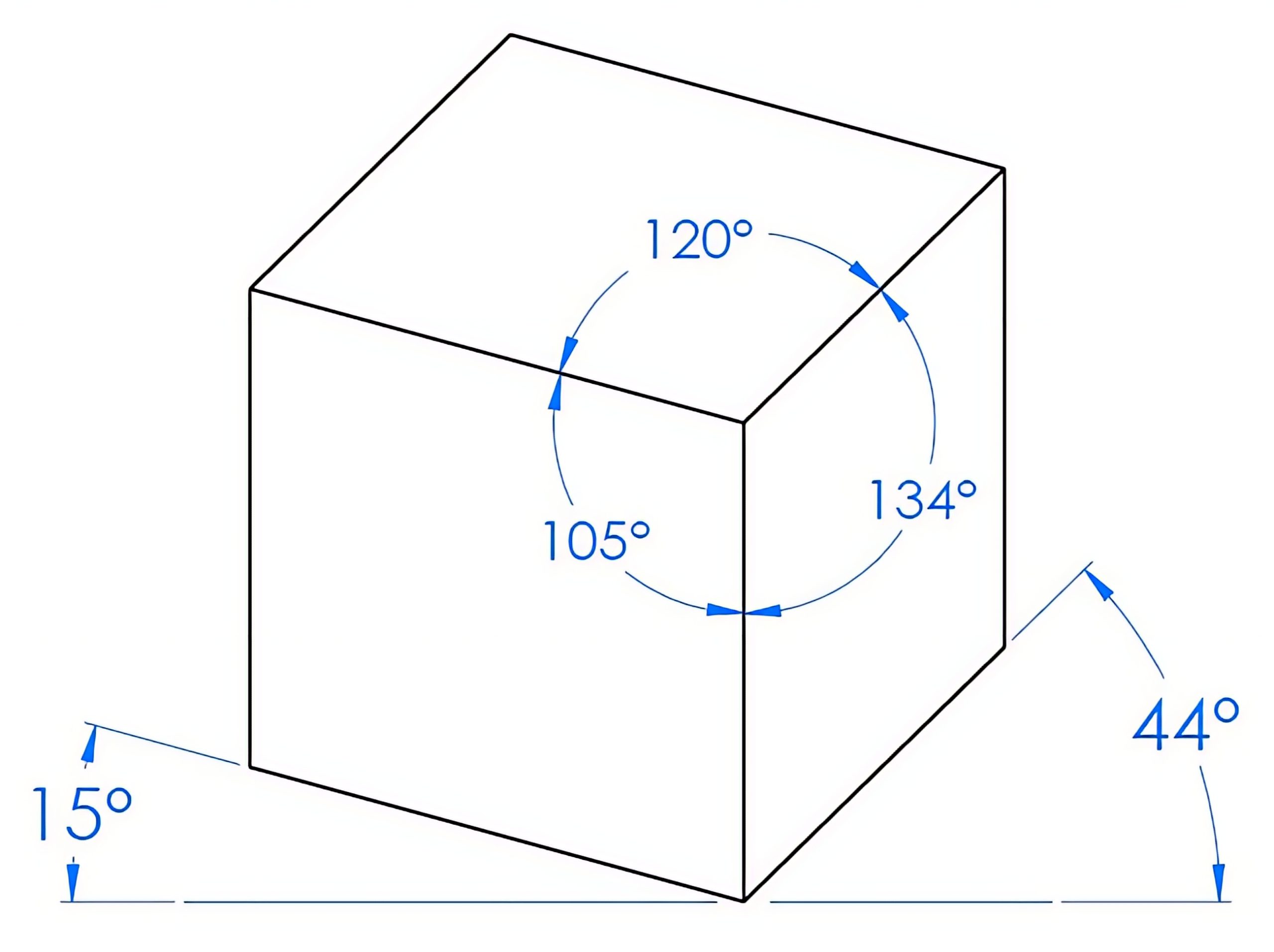
When it comes to pictorial views of objects, three styles are commonly used: isometric, dimetric, and trimetric views. An isometric, meaning “equal measure,” drawing has width, depth, and height features that are all projected 120° from each other, as shown in Figure 4-1. A dimetric pictorial drawing will have two of these three angles drawn equal to each other, as shown in Figure 4-2. A trimetric drawing will have all three angles unequal to each other, as shown in Figure 4-3.
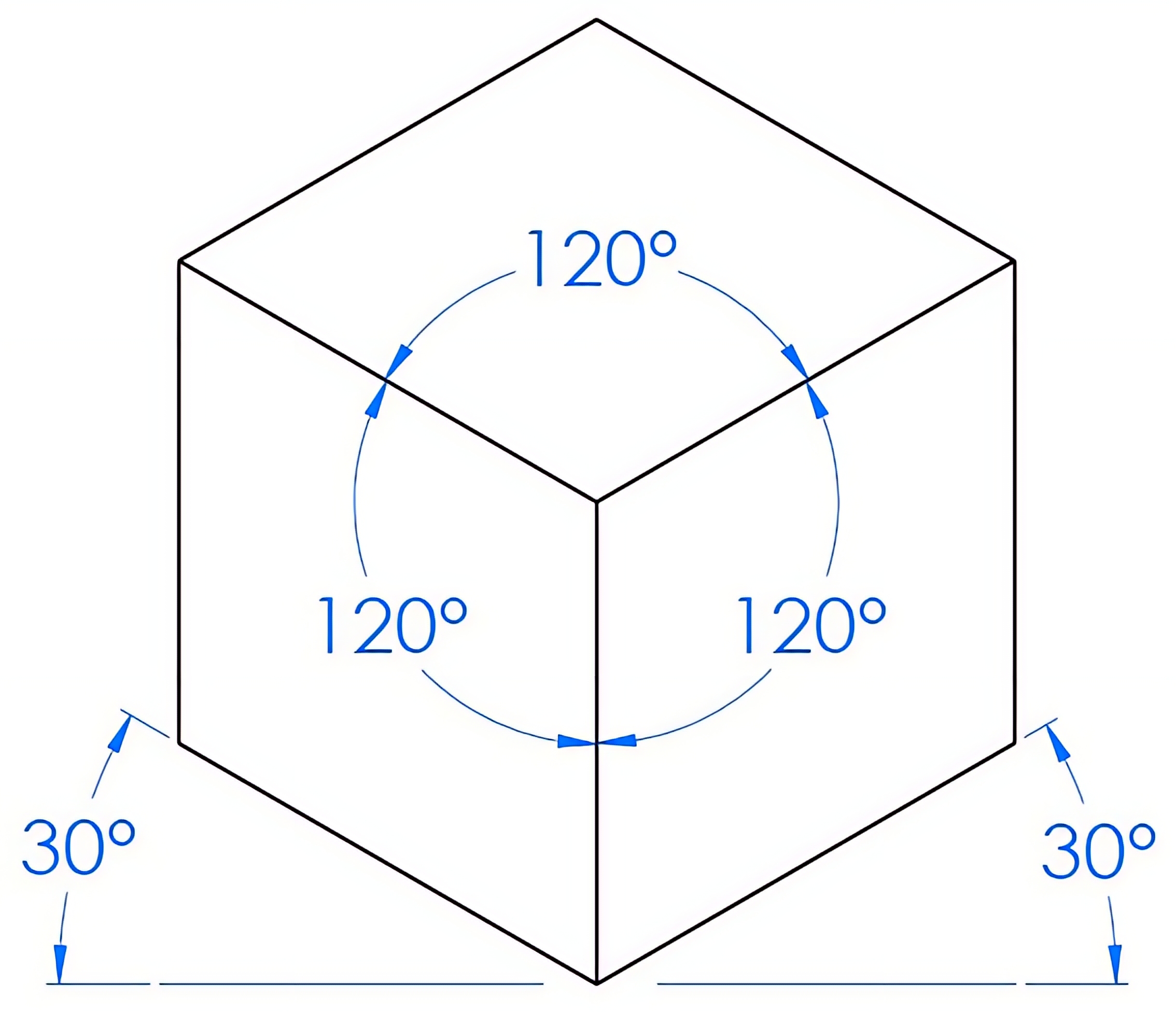
While all three of these pictorial views are sometimes used in computer-aided drafting, the isometric view is most commonly used in sketching. Because the angles are projected equal to each other, isometric sketching can be easier than the other views.
To sketch an isometric drawing view, you can begin in the front corner with one vertical line and lines 30° from the horizontal to the right and the left. See Figure 4-4.
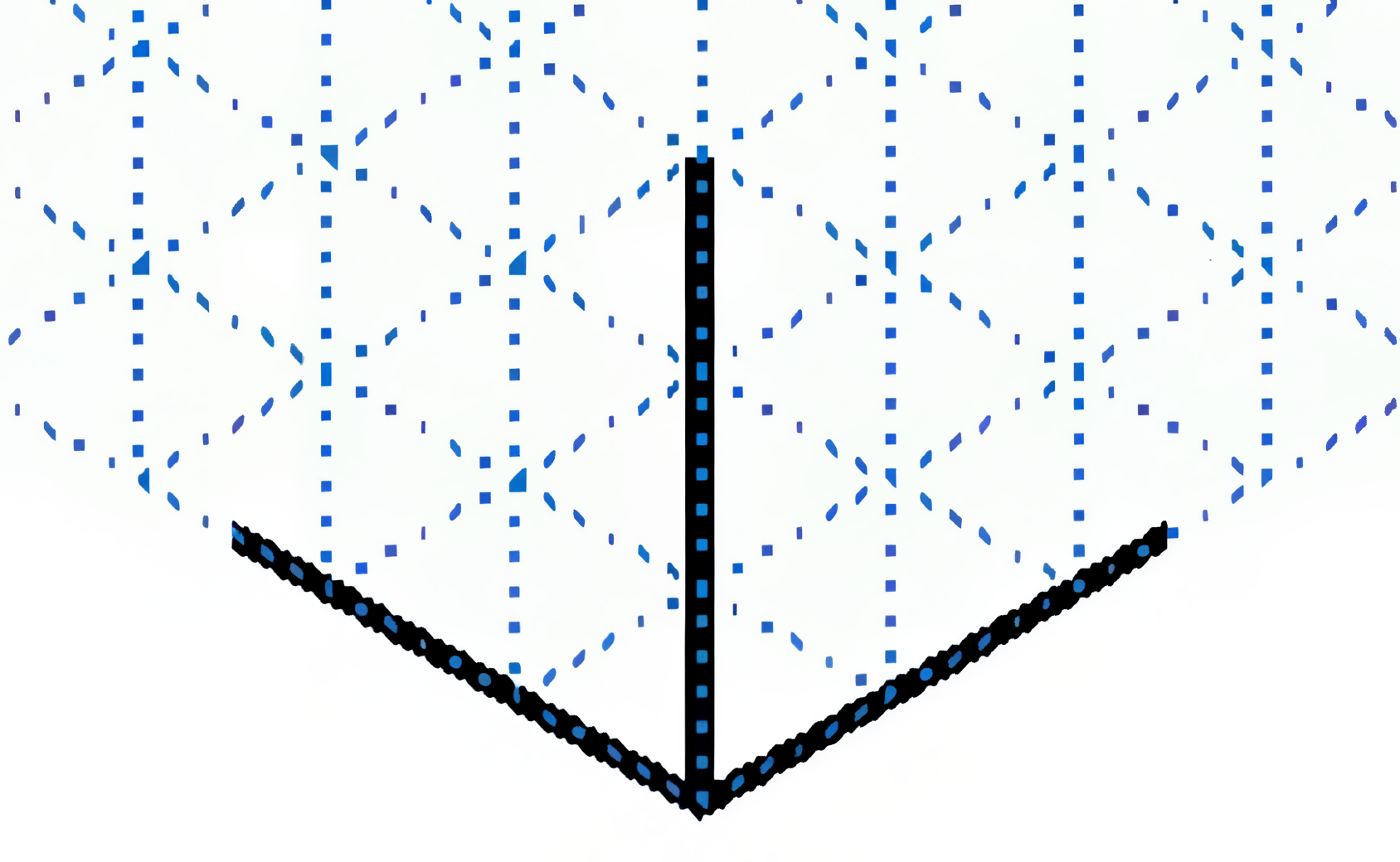
As you sketch, all height lines will be parallel to the vertical line, all right-view horizontal lines will be parallel to the right 30° line, and all front-view horizontal lines will be parallel to the left 30° line. Hidden lines are not typically included in pictorial drawings.
The following YouTube video will illustrate the orthographic views of Isometric Sketch 1 transferred into an isometric sketch.
Learning Activities
Isometric Sketching Exercise
Using your own grid paper, complete the missing isometric views below, using grid lines as a guide. Some sketch lines have been entered to help you get started. Only the visible lines are required. (Solutions are provided in the Learning Activities – Solutions section at the end of the text.)
Isometric Sketching Exercises
Isometric Sketch 1
Isometric Sketch 2
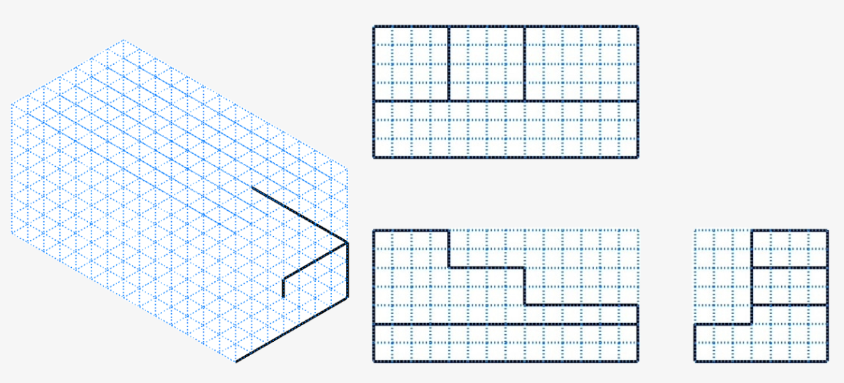
Isometric Sketch 3
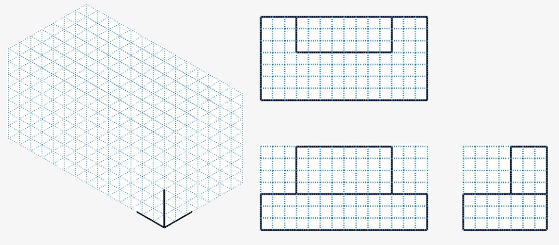
Isometric Sketch 4
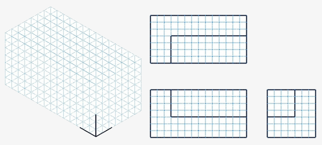
Isometric Sketch 5
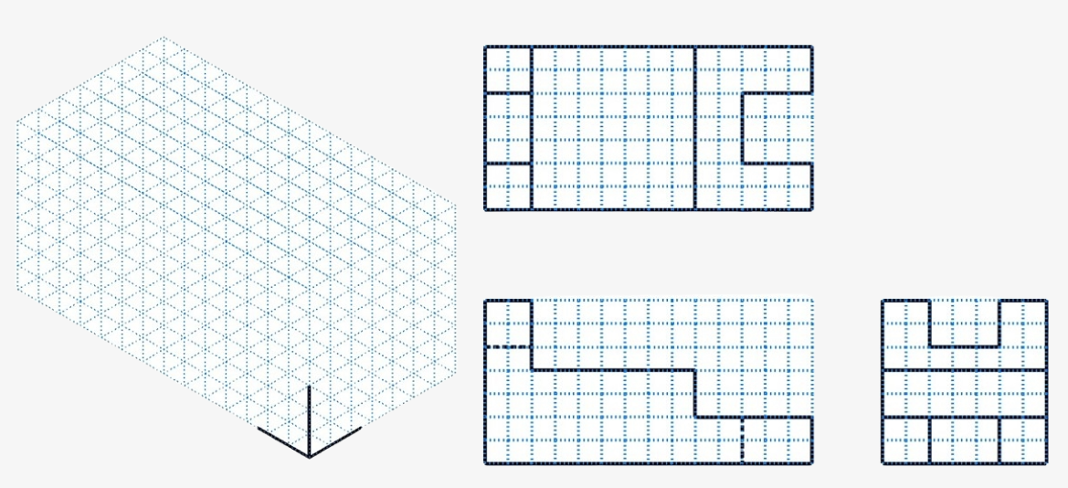
Isometric Sketch 6
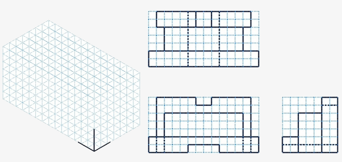
References:
Schultz, R. L., & Smith, L. L. (2012). Blueprint reading for machine trades (7th ed.). Pearson.
Images:
All images by Mark Lorier and licensed under CC BY-NC 4.0 except where otherwise noted.
Videos:
LTC Machining. (2024, November 3). Orthographic sketch exercise 1. [Video]. YouTube. Used with permission. https://www.youtube.com/watch?v=jAH8C7fXjsE
LTC Machining. (2024, November 3). Isometric sketch exercise 1. [Video]. YouTube. Used with permission. https://www.youtube.com/watch?v=oIB2Zbc_MYs

