2. Views of an Object
2.1 Introduction
Learning Objectives
- Identify the primary views of an object
- Select the placement of views on a print
- Differentiate between pictorial and orthographic projection drawings
- Demonstrate the use of projection lines
- Determine appropriate dimensions of length, width, and height related to views
- Differentiate between first- and third-angle projection on prints
- Visualize the basic shapes of objects
Terms
- Multi-view drawing
- Isometric view
- Isometric drawing
- Pictorial drawing
- Orthographic projection
- Oblique drawings
- Perspective drawings
- Principal view
- Height
- Width
- Depth
- Third-angle projection
- First-angle projection
Multi-view drawings are a vital tool in print reading, enabling effective communication and understanding of complex objects. By presenting multiple views, such as the front, top, side, and isometric views, multi-view drawings provide a three-dimensional visualization of an object. They are a universal language in design and manufacturing, ensuring a shared understanding of design intent and specifications. Multi-view drawings also facilitate accurate measurements, precise manufacturing, assembly, quality control, and troubleshooting. Mastering the interpretation of multi-view drawings enhances print readers’ understanding and contributes to successful projects in various industries. In this chapter, we will explore the significance of multi-view drawings in print reading, along with their aid in understanding and interpreting complex objects.
2.2 Multi-View Drawings
Multi-view drawings are an essential component of print reading. They provide print readers with a comprehensive visual representation of an object from different perspectives, aiding in effective communication, accurate manufacturing, assembly, quality control, and maintenance processes. By mastering the interpretation of multi-view drawings, print readers can enhance their understanding of complex objects and contribute to successful projects in various industries. Figure 2-1 is an example of a multi-view drawing displaying the object as it would be viewed from the front, top, and side.

Visualization
Multi-view drawings provide print readers with a three-dimensional visualization of an object. By presenting multiple views, such as the front, top, and side views, print readers can grasp the shape, size, and proportions of the object accurately. An isometric view is a two-dimensional depiction of a three-dimensional object that presents the object’s dimensions and angles from a particular perspective, thereby providing a sense of depth in its representation, as illustrated in Figure 2-2. These three-dimensional views will aid the reader in better understanding the part’s shape and features. This visual representation allows for a better understanding of the object’s design and aids in effective communication among designers, engineers, and manufacturers.

Design Communication
Multi-view drawings serve as a universal language in the design and manufacturing industries. They act as a bridge between different stakeholders, ensuring that everyone involved in the project understands the design intent and specifications. By providing a clear and precise representation of the object, multi-view drawings facilitate effective communication and minimize misunderstandings.
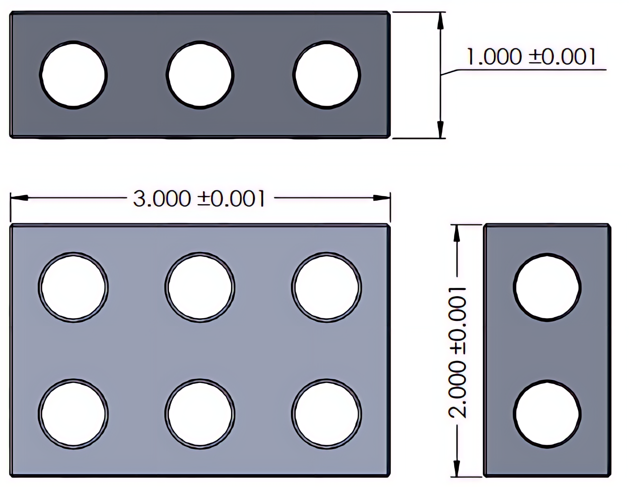
Dimensioning and Tolerancing
Accurate measurements and tolerances are critical in the manufacturing process. Multi-view drawings include dimensions and tolerances that specify the exact measurements and allowable variations or tolerance for each feature of the object. See Figure 2-3. Print readers can interpret these dimensions to ensure precise manufacturing and assembly processes, resulting in high-quality products.
Assembly and Disassembly
Understanding how different parts of an object fit together is essential for efficient assembly and disassembly processes. Multi-view drawings provide print readers with a comprehensive view of the object, allowing them to identify the relationships between components, their orientations, and the sequence of assembly or disassembly. This knowledge ensures smooth and error-free construction or maintenance procedures. In Figure 2-4, the components of an assembly are aligned in relation to how they are to assemble together, along with a list of the parts included in the drawing.

Quality Control
Multi-view drawings serve as a reference for quality control inspections. Print readers compare the actual object or part against the drawing to verify if it meets the specified dimensions, tolerances, and other requirements. This ensures that the final product aligns with the design intent and meets the desired quality standards. Oftentimes, the drawing is considered a contract between a customer and the manufacturer. Ensuring the part passes inspection is a crucial step in maintaining relationships between customers and the manufacturer.
Troubleshooting and Maintenance
Multi-view drawings are invaluable resources for troubleshooting and maintenance purposes. They provide a detailed representation of the object, enabling print readers to identify and understand the internal components, connections, and potential issues. This knowledge aids in efficient problem-solving and maintenance procedures.
Component drawings provide visual depictions of individual parts, as well as their assemblies, aiding technicians in understanding how components integrate and function within a bigger system. These diagrams guarantee accurate identification of components, detailing their dimensions, materials, and specifications—critical factors for ordering replacements that match correctly. In the process of diagnosing problems, component diagrams assist in locating the specific site and nature of issues by enabling technicians to compare the diagram with the actual part and spot any differences. Furthermore, they frequently include essential maintenance details like lubrication points, wear thresholds, and assembly guidelines to ensure that maintenance activities are performed properly. These drawings also serve as invaluable training resources for new technicians by providing a visual reference to the equipment. Ultimately, by offering a clear outline for repairs and upkeep, component drawings help minimize downtime and enhance safety by ensuring all work adheres to established specifications.
2.3 Pictorial Drawings vs. Orthographic Projection Drawings
Pictorial drawings aim to provide a visually realistic and intuitive representation of an object, emphasizing its appearance and overall shape, as shown in Figure 2-5.
An orthographic projection prioritizes accuracy and technical information, providing a detailed and precise representation of an object’s dimensions and features. See Figure 2-6.
Pictorial drawings and orthographic projection drawings are two different approaches to representing three-dimensional objects on a two-dimensional surface. While both methods serve the purpose of visual communication, they differ in terms of the level of realism and the information they convey.
 |
 |
|---|
The views of the orthographic projection drawing will maintain alignment with each other. The front and top views will align vertically, and the front and right views will align horizontally. A 45° projection line can be used as an intersection point to connect projection lines between the top and right-side views, as shown in Figure 2-7.

2.4 Pictorial Drawings
Pictorial drawings, also known as pictorial views or pictorials, are drawings that aim to represent an object in a visually realistic and intuitive manner. These drawings provide a more artistic and subjective representation of the object, emphasizing its appearance and overall shape. Pictorial drawings are often used to convey the visual impact and aesthetic qualities of an object.
There are different types of pictorial drawings, including isometric, oblique, and perspective drawings. In isometric drawings, the object is represented by parallel lines and equal 30° angles, giving the illusion of depth and three-dimensionality. Oblique drawings, illustrated in Figure 2-8, show the object with one face parallel to the picture plane while the other faces are at an angle. Perspective drawings create the illusion of depth and distance by using vanishing points and converging lines, as shown in Figure 2-9.
 |
 |
|---|
Pictorial drawings are useful for presenting an overall impression of an object, showcasing its design and providing a visual representation that is easily understood by non-technical individuals. However, they may not provide precise measurements or detailed information about the object’s dimensions and features.
2.5 Orthographic Projection Drawings
Orthographic projection drawings, often known as orthographic views or multi-view drawings, are a reliable and standardized method for depicting objects. This technique systematically captures an object by projecting it onto planes that are positioned at right angles (90°) to one another.
These detailed 2D representations often feature front, top, and side views of the object. Each view is drawn to a matching scale and aligned with others, ensuring precise measurements and dimensioning. By doing this, these drawings offer a clear representation of the object’s shape, size, and the relationships between its various components.
To create such a drawing, an object is positioned so that each face aligns with one of up to six view planes. Once in place, projections are made onto each plane—resulting in separate front, top, and side views (and more if needed depending on complexity). Some parts, often round parts, may be fully represented in as little as two views (see Figure 2-10). Others may require all six views to fully represent the necessary features as shown in Figure 2-11. Each view shows how the object appears from specific perspectives: head-on from the front view; directly from above for the top view; and straight from either side for side views. The drawing will include the number of views to provide enough detail and information required to manufacture the part and prevent confusion.


Orthographic projection drawings are invaluable for capturing every nuance of an object’s dimensions and interrelationships while ensuring that all measurements remain accurate throughout the design process.
Summary
Unlike pictorial drawings, orthographic projection drawings prioritize accuracy and technical information over visual aesthetics. They are commonly used in engineering, architecture, and manufacturing industries for design, communication, manufacturing, assembly, and quality control purposes.
The main difference between pictorial drawings and orthographic projection drawings lies in their purpose and level of realism. Pictorial drawings aim to provide a visually realistic and intuitive representation of an object, emphasizing its appearance and overall shape. Orthographic projection drawings prioritize accuracy and technical information, providing a detailed and precise representation of an object’s dimensions and features.
2.6 Orthographic View Placement
The relationship between the views can be compared to unfolding a cardboard box. Figure 2-12 illustrates a cardboard box as it is folded into the box shape with the top, front, and right sides identified with their size values.

As you unfold the box, you’ll notice that the views are connected to each other, as shown Figure 2-13. When laid flat, the front surface serves as a central point: the top view is positioned above it, the right view goes on its right side, the bottom view beneath it, and the left view to its left. The back view unfolds further and connects directly to the left view.

In Figure 2-14, you will see that the views are separated but maintain an identical orientation as the unfolded box. These six views are all known as the six principal views. Most part drawings will not use all six views; only the views necessary to communicate the details of the part effectively will be used. A three-view drawing is often sufficient to fully describe a part with the front, top, and right-side views most commonly used. A two-view drawing is typically sufficient for a cylindrical component to communicate the shape and necessary details. Views other than the six principal views are known as auxiliary views. These additional views are discussed in Chapter 12.

To apply this orthographic projection to a part drawing, the part can be viewed as if it is placed inside a box with the part views projected onto each surface. Figure 2-15 displays a part placed inside a clear box. Unfolding or rotating this box using the orthographic projection view placement will produce the six principal views of the part shown in Figure 2-16.


2.7 Names of the Views
The names of the views on an orthographic print are not as important as the relationship between each view. The front view will typically provide the best representation or profile of the part being drawn. An example of this would be if a car were to be drawn in orthographic projection. The side view of the car would likely be used as the front view on the print because it would show a more distinguishing profile than what the front of the car would show.
Observe the difference in how the views are arranged for the block in Figures 2-17 and 2-18. Each drawing provides a clear representation of the identical block. The relationship between the views is more important than the name of the view.


2.8 Height, Width, and Depth
The common terminology used when referring to an object’s overall size is height, width, and depth. It is important to use these standard terms correctly when referring to a part’s size (see Figure 2-19). Because the three-dimensional parts are projected to a two-dimensional view, only two of these three values may be observed from any one view; the third value would be found in one of the perpendicular views. An object may also be described using the terms “length” and “thickness.” When these terms are used, the thickness will refer to the smallest outside value, and the length will be the longest value.
The height of the part is the distance between the top and bottom of the part. Because the height cannot be observed in the top view, the height measurement will only appear in the front, back, or side views.
Width, also called length, is the distance between the left and right sides of the part and can only be visible in the front, back, top, or bottom views. The width measurement cannot be observed in the side views.
The depth, sometimes referred to as the thickness, is from the front of the part to the back of the part. The depth measurement can only be seen in the top, bottom, or side views.
See Figure 2-19 below for an illustration of height, width, and depth.

View the supplementary YouTube video for further explanations and visual examples on how to distinguish between height, width, and depth measurements: Height, Length/Width, and Depth dimensions on blueprints
2.9 Projection Views
When vertical and horizontal viewing planes intersect each other, four separate quadrants are created: first, second, third, and fourth. See Figure 2-20. If an object is placed in the first quadrant, the views are projected back to the vertical plane and down to the horizontal plane. When an object is placed in the third quadrant, the views are projected forward to the vertical plane and up to the horizontal plane. This results in two distinct methods for projecting or positioning the two-dimensional representations of a three-dimensional object on a drawing sheet. An object placed in the second or fourth quadrant would create the same resulting views of the first and third and are, therefore, not used.

When the first quadrant projection style is used for a multiple-view drawing, it is known as first-angle projection. In Figure 2-21, you will see that as the viewing planes are laid flat, the resulting placement leaves the top view below the front view.

When the third quadrant projection style is used for a multiple-view drawing, it is known as third-angle projection. In Figure 2-22, as these views are laid flat, the top view is now placed above the front view.

The two views of the cone-shaped object are placed on drawing sheets to identify which view style is being used. Either first-angle (Figure 2-23) or third-angle projection (Figure 2-24) will be identified by the placement of the two views of this or a similar object’s views. The words “first angle” or “third angle” may be used in place of these views on a drawing sheet as well.


Visit GD&T Basics’ First vs Third Angle – Orthographic Views for additional information on identifying first- and third-angle projection in orthographic projection drawings.
2.10 Third-Angle Projection
The layouts of the views we’ve explored so far have been presented using third-angle projection. This method of creating multi-view drawings has been the standard in North America since the early 1900s. Third-angle projection was adopted because it offers a more intuitive way to arrange views within a drawing. Just like an unfolded box, you’ll see the top view directly above the front view and the right view positioned to its right, making everything easier to understand at a glance, as shown in Figure 2-25. Observe the third-angle projection symbol in Figure 2-25 as well.

2.11 First-Angle Projection
While the third-angle projection is the standard method used in the United States and Canada, a slightly different projection method is used in most other industrial nations. In first-angle projection, the views surrounding the front view are reversed when compared to third-angle projection. Observe Figure 2-26 where the top view is placed below the front view, and the right view is to the left of the front view.

View Third Angle Projection Vs First Angle Projection YouTube video for an additional resource.
Take a moment to notice the differences in how views are arranged around the front view when comparing first-angle and third-angle projections. Pay close attention to the “cone” symbol as well—it follows the same orientation rules for both styles. Given that many industries operate on an international scale, it’s crucial to get into the habit of identifying which projection style is being used before diving into any drawings. Your awareness can prevent misunderstandings and ensure smooth communication across borders.
Learning Activities
View Identification Quiz
Note: To enlarge this image, simply click on the plus sign icon in the upper right-hand corner of the print.
Surface Identification Quiz 1
Directions: Click and drag each letter in the gray boxes below to their corresponding open circle according to its surface identification.
Surface Identification Quiz 2
Directions: Click and drag each letter in the gray boxes below to their corresponding open circle according to its surface identification.
References:
Schultz, R. R., & Smith, L. (2011). Unit 1: Dictionary of Terms. Standard Abbreviations. Alphabet of Lines. In Blueprint reading for machine trades (7th ed.). Pearson.
Images:
All images by Mark Lorier and licensed under CC BY-NC 4.0 except where otherwise noted.
Videos:
Skeen, C. (2013, October 3). Height, Length/Width, and Depth dimensions on blueprints [Video]. YouTube. All rights reserved. https://www.youtube.com/watch?v=dqS-atGfsH4
Maker Clan. (2014, September 27). Third angle projection vs first angle projection 3D part 1 [Video]. YouTube. All rights reserved. https://www.youtube.com/watch?v=bk2E8P33Ztc
