14. Print Specifications
14.1 Introduction
Learning Objectives
- Select material for layout
- Apply layout dye per procedural guidelines
- Select baselines for layout (select appropriate surfaces)
- Calculate dimensions
- Scribe lines for appropriate dimensions and detail
- Compare layout to print specifications
Terms
- Layout fluid
- Scriber
- Surface plate
- Height gauge
- Angle plate
- Surface gauge
- Protractor
- Sine bar
- Divider
This chapter will apply the skills from previous chapters to perform an accurate layout of feature locations obtained from the print specifications. A layout fluid will be applied to the material selected, with feature locations that are properly located to serve as a guide for machining operations.
14.2 Layout Fluid
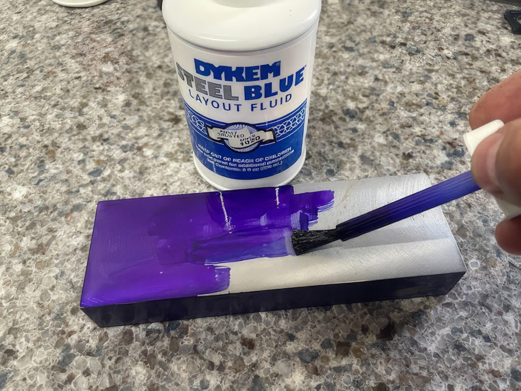
Layout fluid, also called layout dye, is applied to a part surface to provide a contrast for the layout lines. The fluid, typically a dark red or dark blue, is applied in a thin, even coat using an in-cap applicator or aerosol spray. The fluid will dry quickly once applied, and it should be completely dried before handling. Figure 14-1 shows an example of layout fluid.
14.3 Scribing Lines
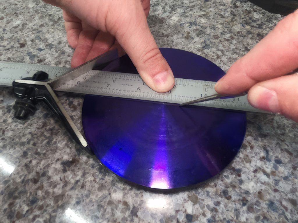
Lines are often created using scribers, along with a straight edge such as a combination square. A scriber is a sharp, fine-pointed tool used to create an accurate straight line on the laid-out surface. The scriber is best used by pulling or dragging along the straight edge. Pushing the scriber can cause the sharp point to catch on the material or straight edge, preventing a straight, even line. See a scriber in Figure 14-2.
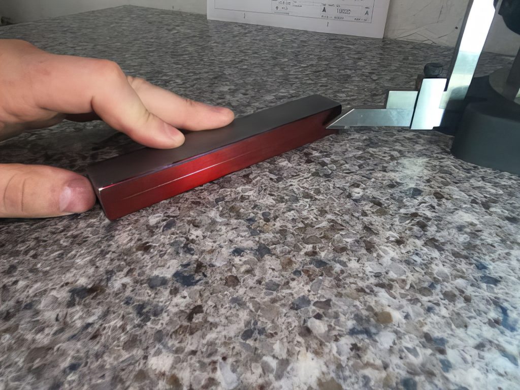
A surface plate and height gauge, or surface gauge, may also be used to create straight scribed lines. A surface plate is a solid, flat plate used as the main horizontal reference plane for precision inspection and for layout to create straight parallel scribed lines. A height gauge is a precision measuring tool used to determine the height of an object. Using a height gauge on a surface plate has the advantage of setting the scribing edge to an accurate height without having to use another measuring tool. In Figure 14-3, a straight fine line is scribed by dragging the part along the scribe of a height gauge using a surface plate as a reference surface.
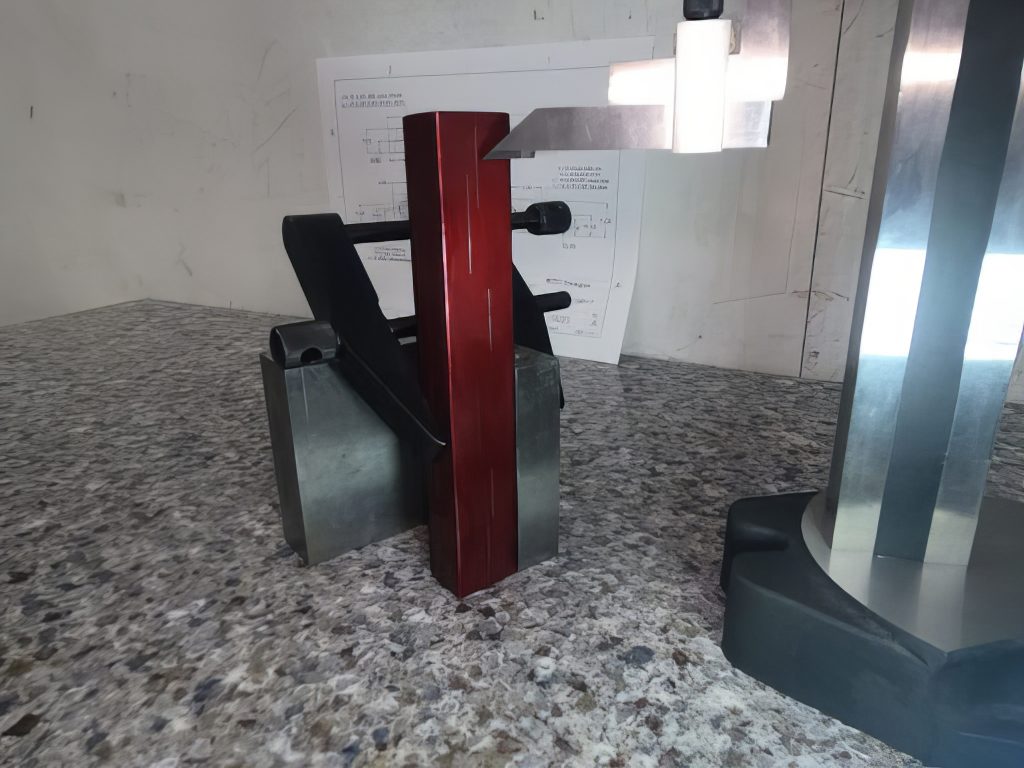
An angle plate is an L-shaped component with a precision right angle used for clamping work in a vertical position for inspection, machining, or layout. In Figure 14-4, an angle plate is used to secure the part in an accurate vertical position for layout with a height gauge.
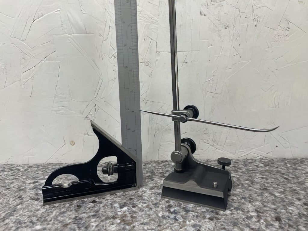
A surface gauge is a versatile tool made of a solid base and adjustable arm with sharp ends often used for scribing. The surface gauge arm can be accurately adjusted to a height using a secondary measuring tool such as a steel rule shown in Figure 14-5.
14.4 Scribing Angles
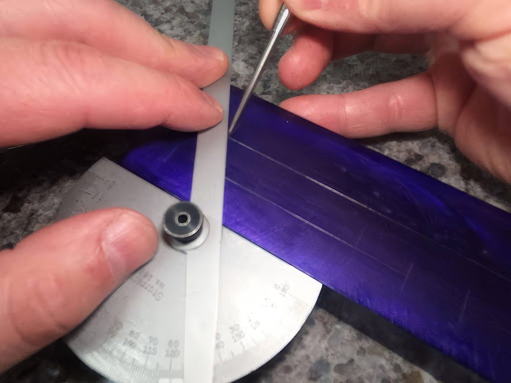
Angles can be scribed using a combination square protractor or a plain protractor, also called a plate protractor. A protractor can be used to both measure angles and locked at an angular position to the nearest degree to be used for angular scribing. In Figure 14-6, the protractor is locked to a specified angle for scribing. To accurately scribe the angle, the straight edge of the protractor’s head is moved to the reference edge of the workpiece, and then the scriber is dragged along the blade edge.
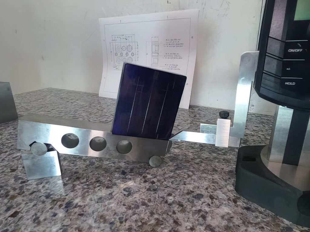
A sine bar may also be used for angular measurements. A sine bar is a tool used along with an accurate stack of blocks known as gauge blocks to create a precise angle. A sine bar creates the hypotenuse of a right triangle to set an accurate angle. To calculate the height of the stacked blocks needed, multiply the sine of the angle by the length of the sine bar. In Figure 14-7, a sine bar is set to an angle on a surface plate to scribe an accurate angular line with a height gauge.
14.5 Scribing Arcs
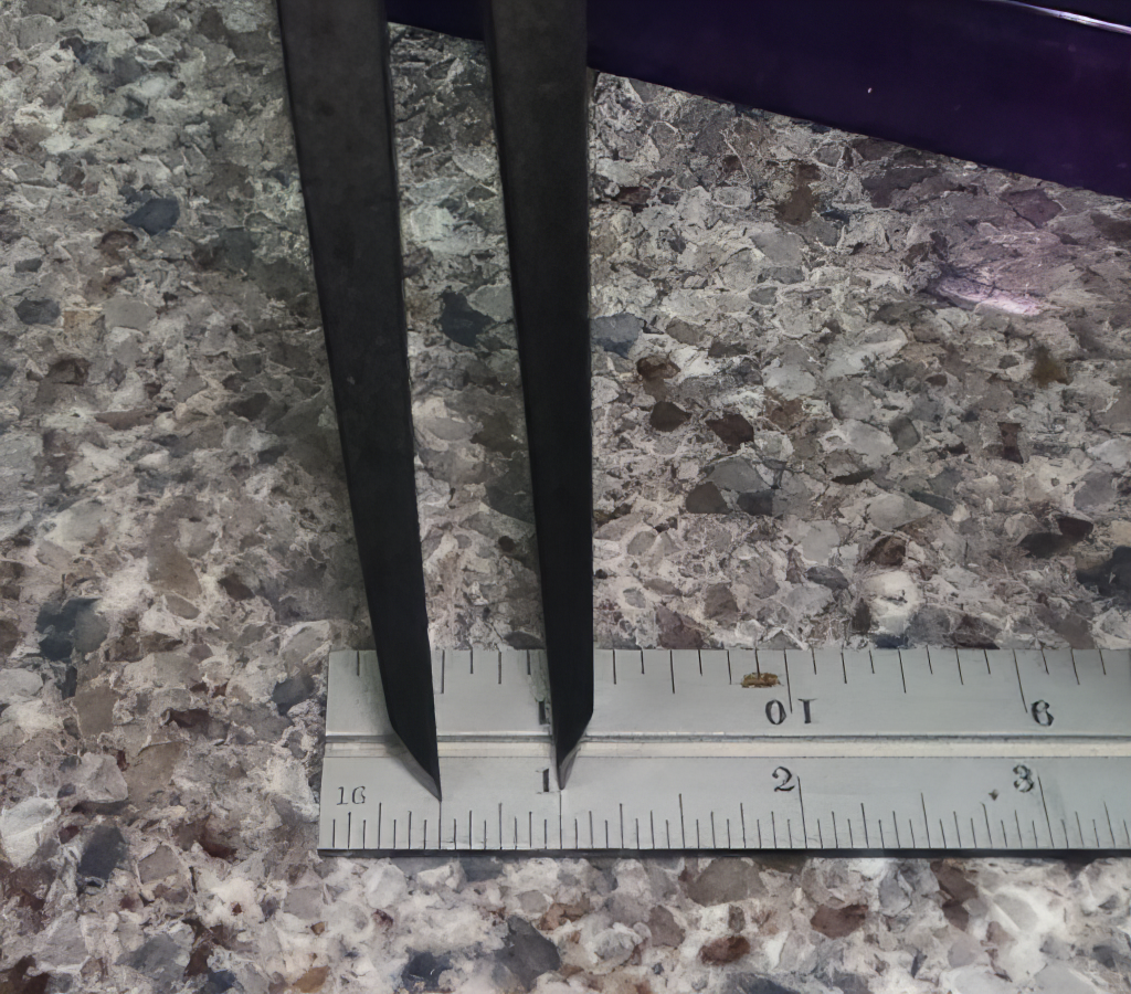
A divider is a scribe tool with two adjustable points for scribe circles, arcs, and radii. A divider is set to the radius of the desired arc, often using a ruler with one point placed on the 1-inch line and adjusting to the desired radius. See Figure 14-8.
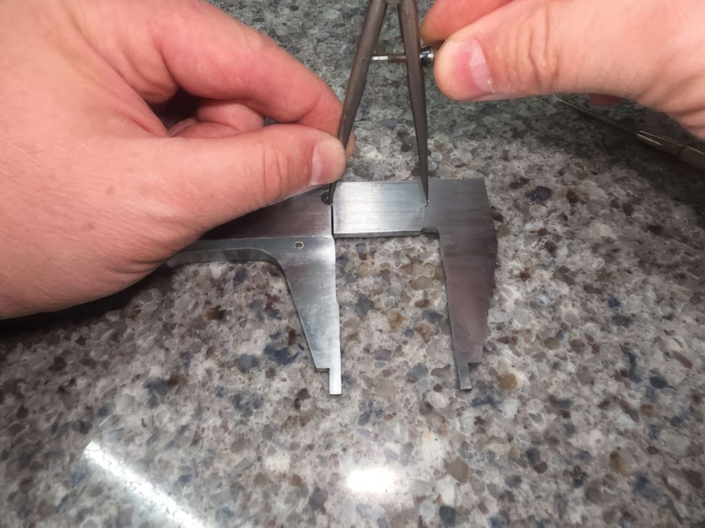
Some calipers will provide indentations on the back side to allow for a more accurate divider setting. View Figure 14-9.
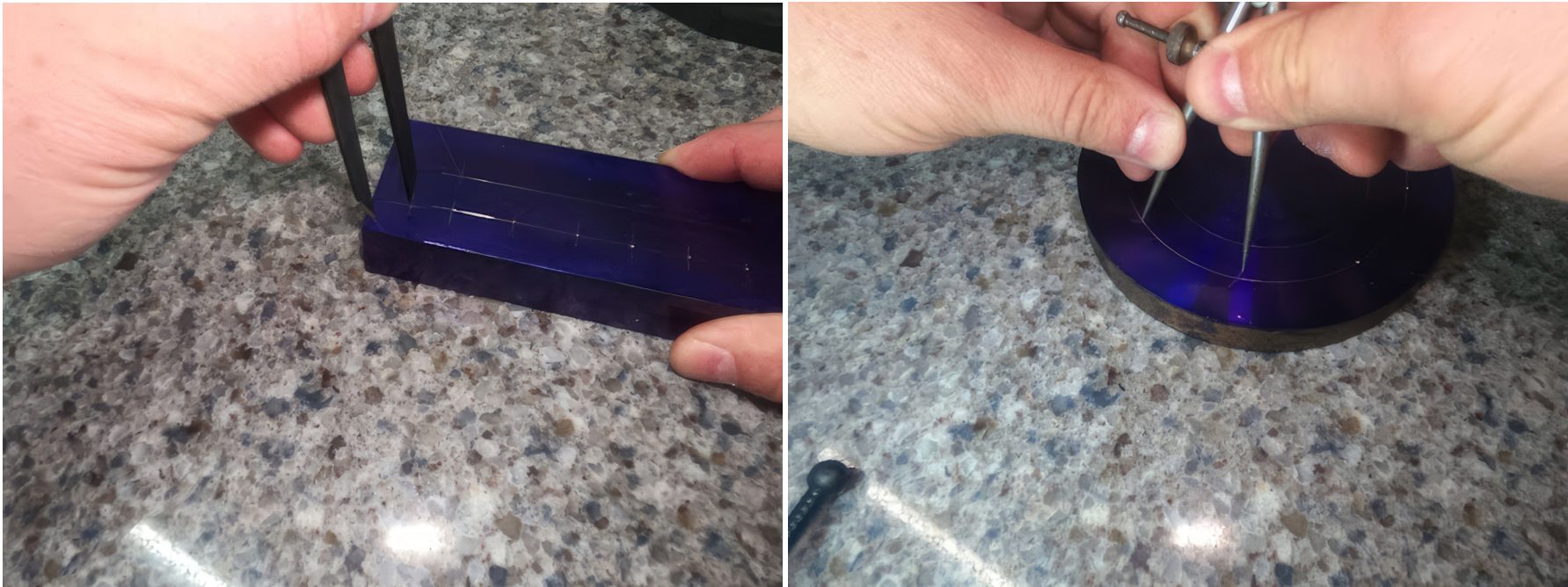
To scribe, one point of the divider is held in the arc’s center point, and the other point is pulled to create the scribed arc, as illustrated in Figure 14-10.
Learning Activities
Exercise 14.5-1
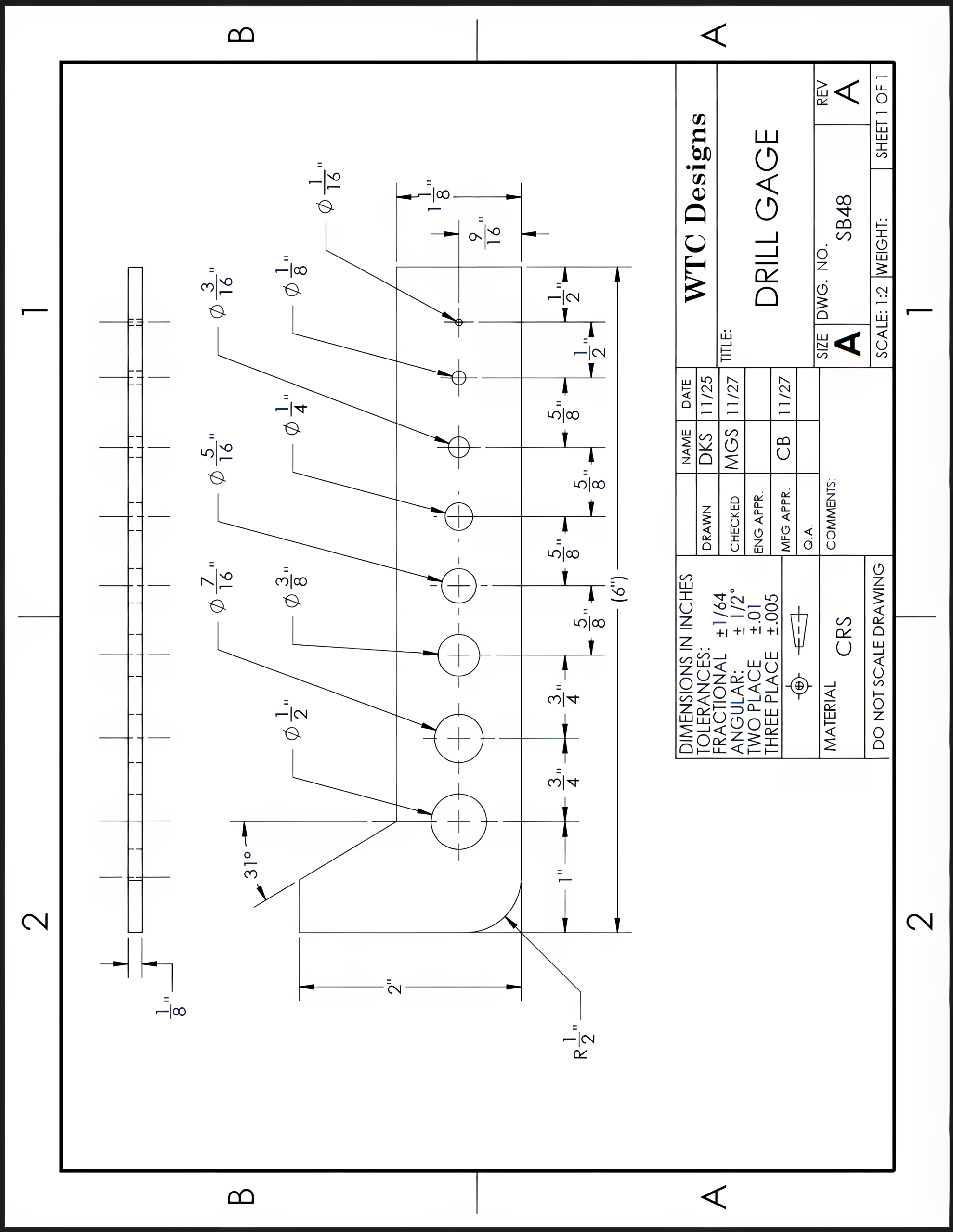
Use 1/8″ x 2″ x 6″ material to layout and scribe this workpiece according to the print.
Exercise 14.5-2
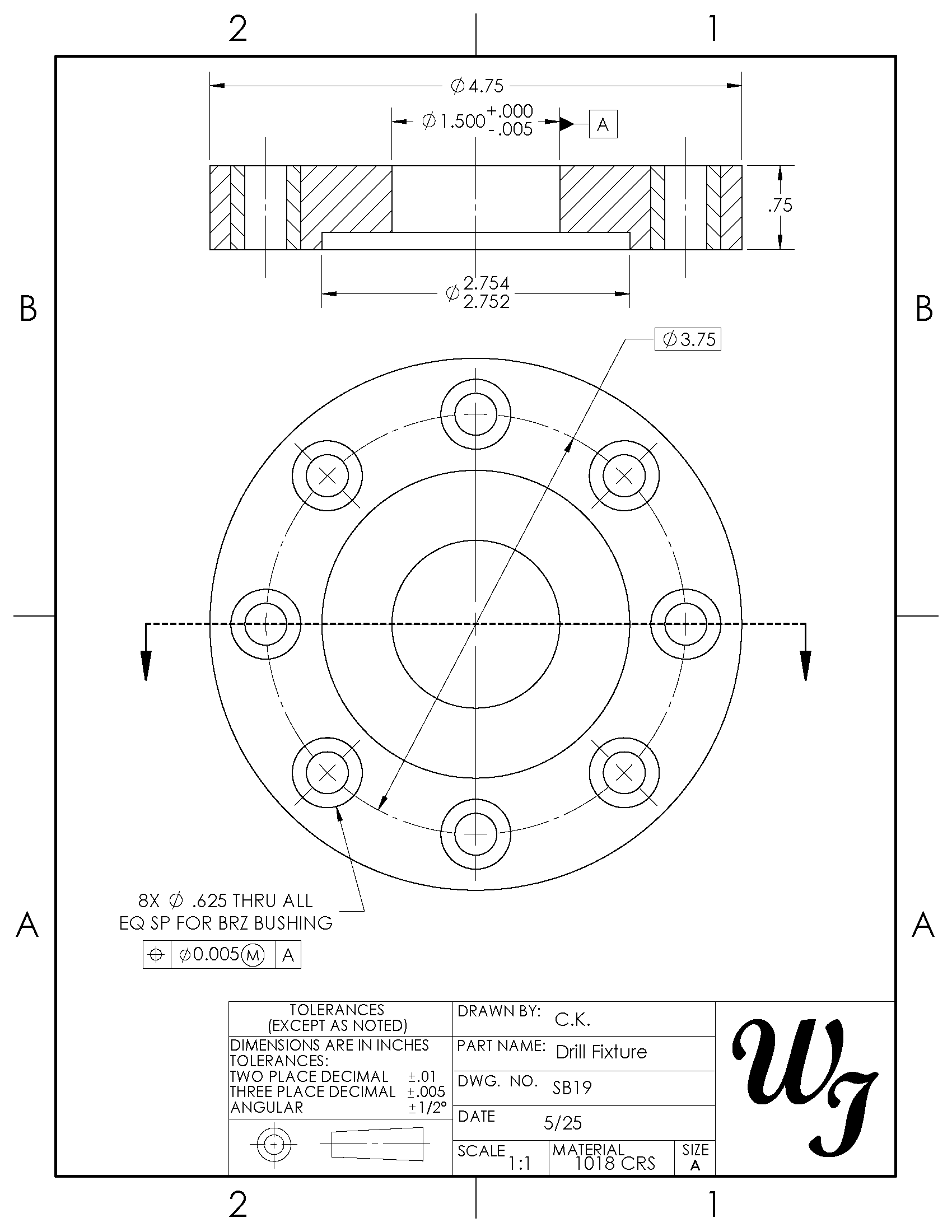
Use .75″ x 4.75″ diameter material to scribe the circles for the 1.500″, 2.754″/2.752″, and 3.75″-diameter circles. Consult the Machinery’s Handbook for the “Chord Length for Given Number of Divisions” for the diameter of the bolt circle and the number of holes required to find the distance to set the divider to lay out the bolt hole locations, as shown in Figure 14-10.
Exercise 14.5-3
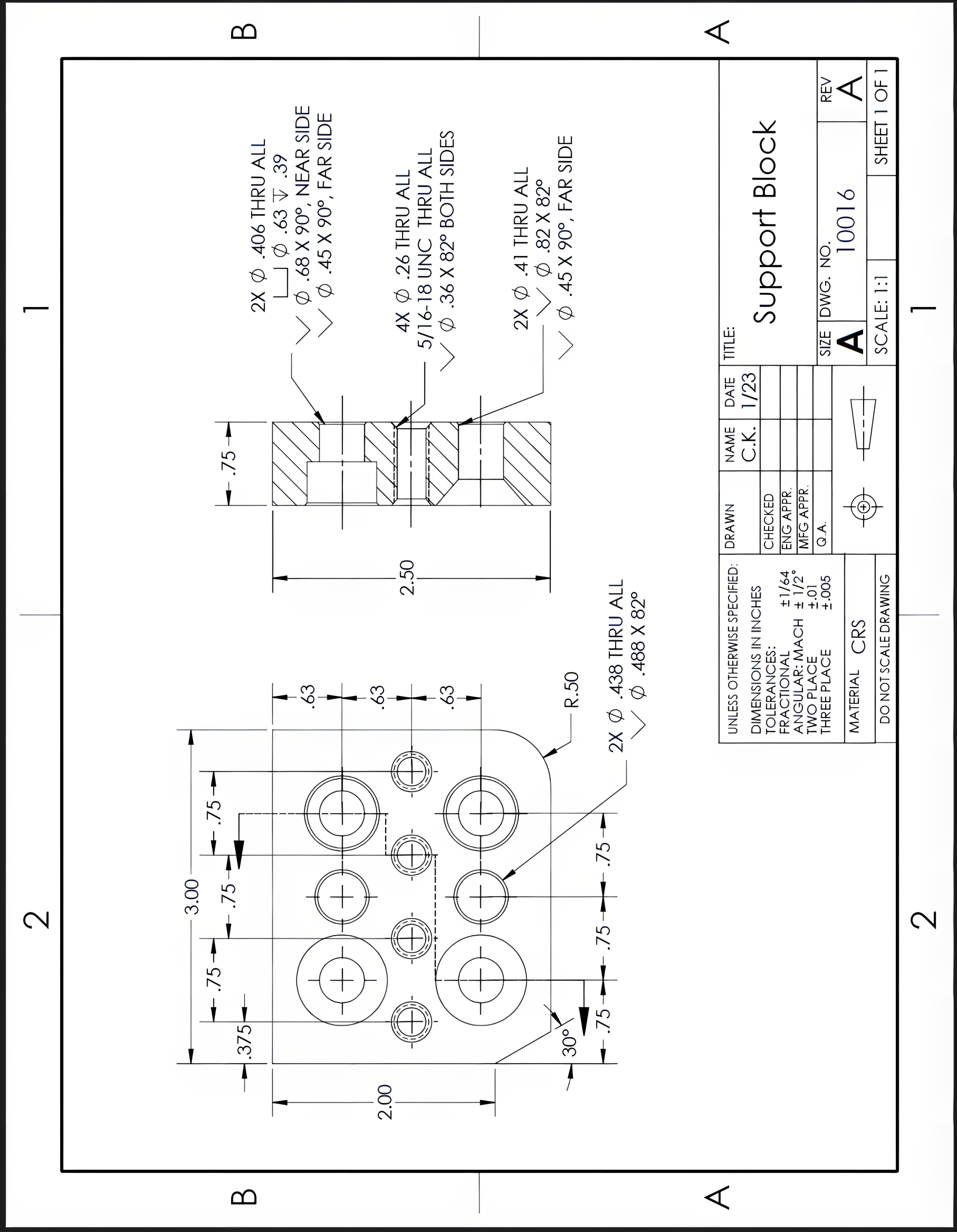
Using .75″ x 2.50″ x 3.00″ material, layout and scribe this workpiece according to the print.
Exercise 14.5-4
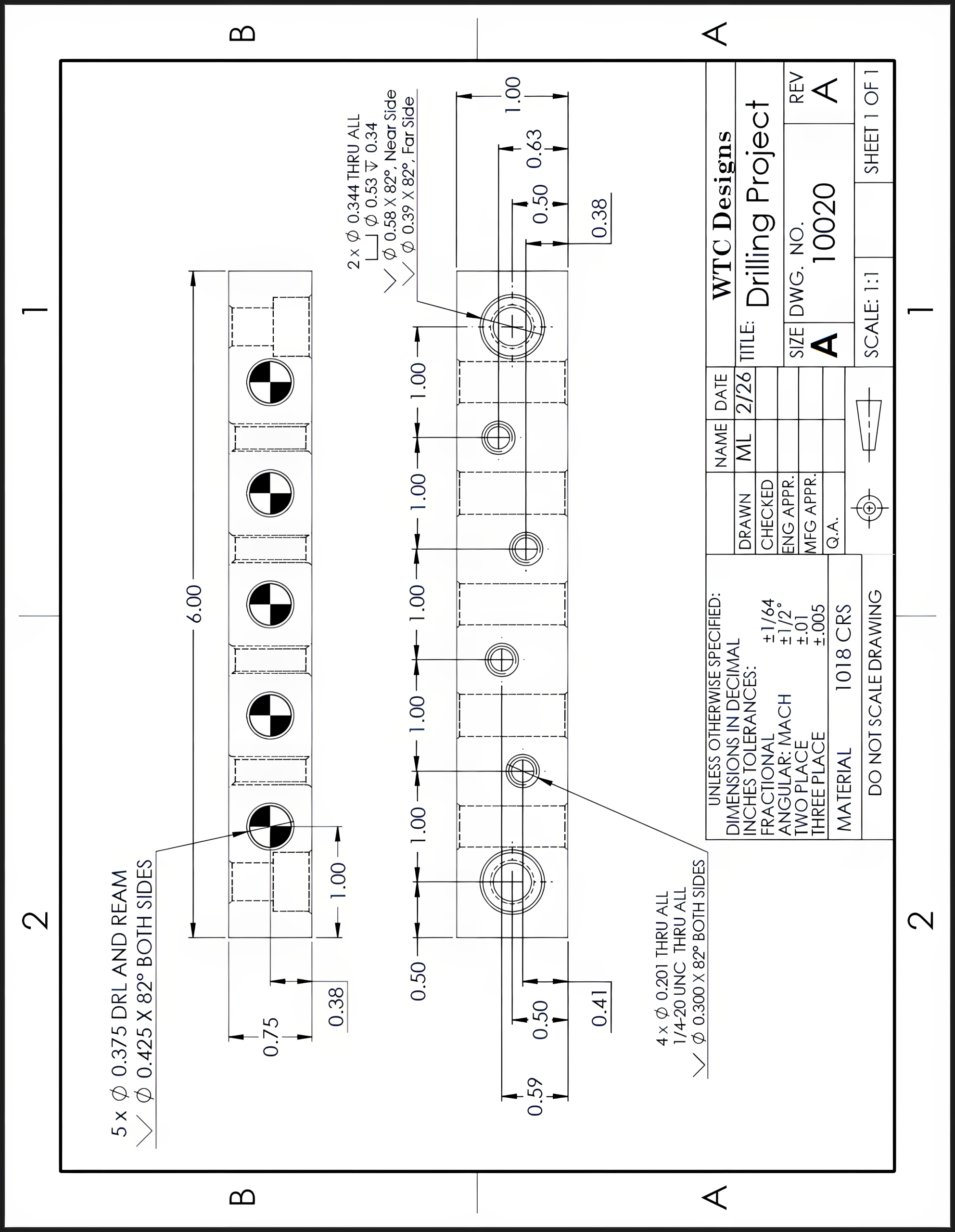
Using .75″ x 1.00″ x 6.00″ material, layout and scribe this workpiece according to the print.
References:
Hoffman, P. (2020). Section 3: Unit 2. Layout. In Precision machine engineering (3rd ed.). Cengage Learning.
Images:
All images by Mark Lorier and licensed under CC BY-NC 4.0 except where otherwise noted.

