12. Auxiliary Views
12.1 Introduction
Learning Objectives
- Identify auxiliary views
- Interpret details on auxiliary views
- Determine dimensions on auxiliary views
Terms
- Inclined plane
- Foreshortened view
- True shape
- Curved surface
- Auxiliary view
- Secondary auxiliary view
- Partially enlarged view
Typically, the six main views—front, back, top, bottom, right, and left—will cover all the essential information you need. However, there are instances where a print might need extra views to convey its features and dimensions fully. For example, when a part has an angled surface, the standard views will not show that surface’s actual shape directly. In this case, including an additional view to represent the surface is helpful. This additional perspective can better represent the actual shape of that surface and accurately show where important features are located.
12.2 Inclined Planes
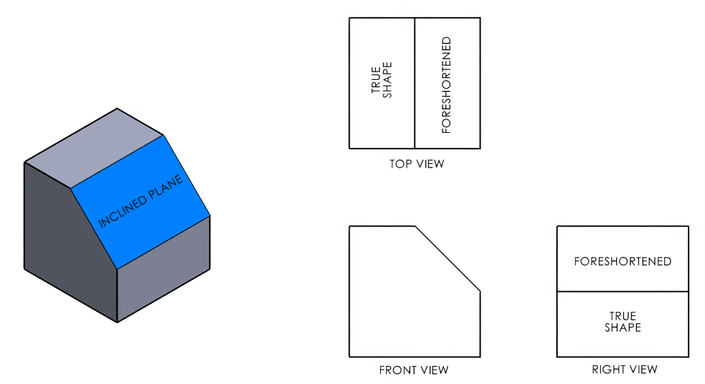
An inclined plane is any surface that isn’t aligned parallel to the two-dimensional projection planes in an orthographic view. Because of this angle, these inclined planes don’t appear in their actual shape when represented visually. When we project these surfaces onto the principal planes, the actual size and form of that plane appear smaller than they truly are; this phenomenon is known as a foreshortened view. When the view presents the part or feature in its actual shape, this is referred to as its true shape.
In Figure 12-1, notice the width of the inclined plane surface appears shorter when projected to the top and right views. Also, observe the visible line in the middle of the top and right-side views representing the intersection of the surfaces.
12.3 Curved Surface
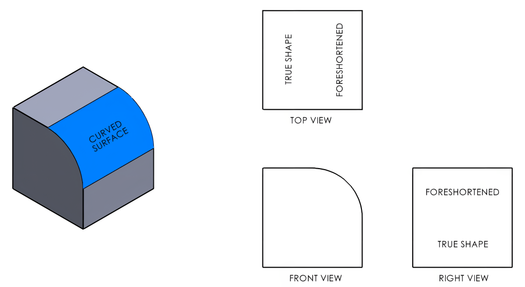
Just as an inclined plane, or angled surface, will create a foreshortened view, a curved surface will create a foreshortened surface when projected to the orthographic views as well. In Figure 12-2, notice that the radius would not be represented in the top or right views. When a curved surface runs tangent to another surface, often a visible line will not be drawn to represent this transition.
12.4 Auxiliary View
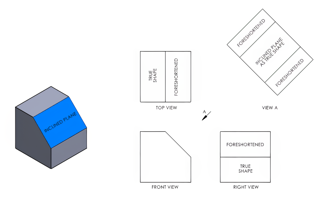
When the true shape of a part’s surface or features cannot be shown in any of the six principal views, an auxiliary view is necessary. An auxiliary view is a view that is not aligned with the principal views used to present an inclined surface or feature in its true shape. An auxiliary view may be an additional view, or it may be used to replace a primary view.
In Figure 12-3, View A is an auxiliary view projected in line from the front view’s inclined surface. This auxiliary view now displays the inclined plane in its true shape, allowing sizes and features to be properly dimensioned. Notice that the other two surfaces in View A are now foreshortened.
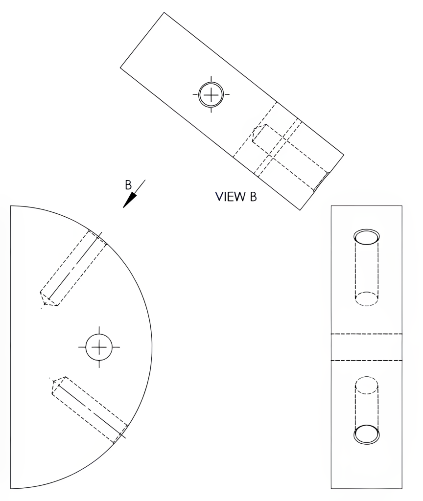
An auxiliary view may also be projected from a feature such as a hole, as in View B, shown in Figure 12-4. In the View B example, this view is projected in line with the drilled hole.
12.5 Secondary Auxiliary Views
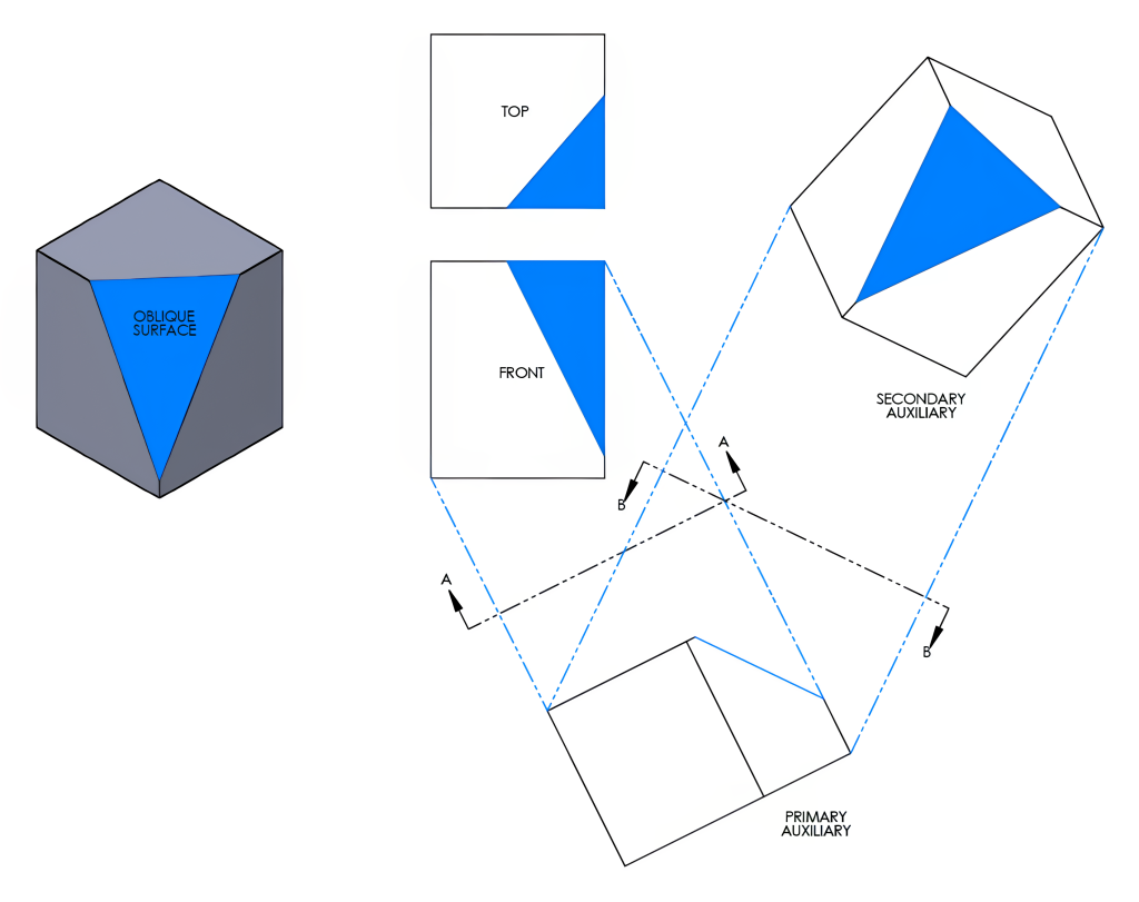
Surfaces that are at an angle to all of the principal planes are known as oblique surfaces. To show an oblique surface as a true shape, a secondary auxiliary view is necessary. A secondary auxiliary view is projected from a primary auxiliary view to properly display an oblique surface. A viewing-plane line and identifying view label may be omitted on a clearly represented auxiliary view. Figure 12-5 uses a secondary auxiliary view to view the oblique surface as a true shape.
12.6 Partially Enlarged Views
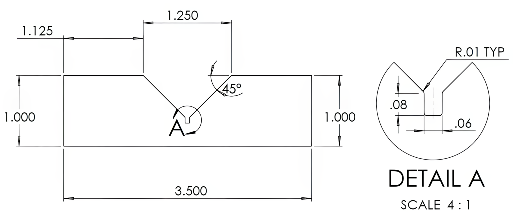
When smaller details of a drawing are too small to easily be dimensioned, just that portion of the drawing may be increased to a larger scale. These partially enlarged or detailed views will be placed elsewhere on the print and identified with the view letter. They will also have their own increased scale located beneath the view. This allows for clearer dimensioning for these details without increasing the scale of the entire drawing. Figures 12-6 and 12-7 use a partially enlarged view to show the detailed portion on a larger scale. The location from which this view is removed will be identified on the main view with a letter and circular shape that is being enlarged.

Learning Activities
Exercise 12.3-1 Surface Identification
Enter the letters that correspond to the correct spaces within the green circle of each slide.
Exercise 12.3-2 Surface Identification
Enter the letters from the isometric drawing below into the top of the correct balloons and indicate whether it is a true shape view with a “T,” an inclined surface with an “I,” or a curved surface with a “C” in the bottom of the balloon on the orthographic view.
Exercise 12.4-1 Auxiliary View
Exercise 12.4-2 Auxiliary View
Exercise 12.6-1 Auxiliary View
References:
Barsamian, M. A., & Gizelbach, R. (2022). Machine trades print reading. Goodheart-Willcox.
Schultz, R. L., & Smith, L. L. (2012). Blueprint reading for machine trades (7th ed.). Pearson.
Images:
All images by Mark Lorier and licensed under CC BY-NC 4.0 except where otherwise noted.

