11. Section Views
11.1 Introduction
Learning Objectives
- Define section terminology
- Identify various section lines
- Interpret different types of sectional views
Terms
- Sectional view
- Full section
- Half-section
- Offset section
- Broken-out section
- Revolved section
- Removed section
Sectional views are a powerful tool that allows engineers, designers, and technicians to visualize the internal features of an object or component that cannot be seen in a regular orthographic view. By cutting or slicing through an object, a sectional view reveals the hidden details, such as internal structures, cavities, and complex geometries.
There are several different types of sectional views, including full sections, half-sections, offset sections, broken-out sections, revolved sections, and removed sections. These views are often an additional view placed somewhere on the drawing sheet but may also replace one of the primary views as well.
This chapter will cover the principles and techniques of interpreting sectional views, including the use of cutting planes and section lines. We will also discuss the importance of the dimensions and annotations of sectional views to convey critical information about the object’s internal features.
11.2 Sectioning Principles
A sectional view represents the part of an object remaining after a portion has been imaginarily “cut” with a cutting-plane line, revealing the interior features. With the exception of some features such as thin ribs or spokes, the material that has cut through is represented with section lines. The diagonal and parallel section lines, known as the cast iron section line, are most commonly used for general purposes; however, the designer may use the material-specific sectioning style when called for. Some examples of the material-specific section styles are shown in Figure 11-1.

Line Orientation
A section view will reveal features hidden in other views, allowing these features to be drawn with visible lines rather than hidden lines. To avoid confusion, any remaining hidden features are not represented in the section view. The general section line pattern and angle may be adjusted for clarity to differentiate between separate components in an assembly and when the lines may run parallel to the parts’ visible lines, as illustrated in Figure 11-2.

Thin Features
When the cutting plane line passes through a thin web or rib feature, the section lines will not be included for that portion to avoid a false sense of thickness for this feature. See Figure 11-3.

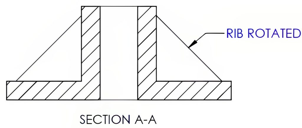
Rotated Features
When a sectioned object contains features such as holes or ribs that rotate around a common center point, these features may not be aligned with the cutting-plane line. When this occurs, the features may appear distorted because they are being seen at an angle to the section view and not perpendicular to it. Figure 11-4 shows the sectioned view as it would appear in the view; the rib on the left shows the actual shape, while the right appears distorted due to the perspective of the view. Traditional practice is to rotate these features in the section view to appear as their actual shape, as shown in Figure 11-5. Before CAD, this practice of rotating these features also made the drawings easier to create for the manual draftsperson. Today, with CAD-created drawings, this practice is no longer as prevalent as it once was.

11.3 Full Section
A full section view is one in which the cutting-plane passes straight through the entire portion of the part where the cutting-plane line is placed as if the part were cut into two pieces. The cutting-plane line will be shown with the arrows indicating the direction in which the removed view is observed. The letters on the cutting-plane line will match the letters of the sectioned view to reduce confusion when multiple cutting-planes or viewing-planes are used on the drawing. If the sectioned view has a clear source, the identifying letters may be omitted.
Notice the hole in Section B-B is not represented with hidden lines as shown in Figure 11-6. Hidden lines are typically omitted when section views are used because the internal features will be viewed in the sectioned view.

11.4 Half-Section
A half-section view will show only half of the part sectioned. Rather than cutting straight through the part, the cutting-plane line is drawn to the center and turns 90° to remove one quarter of the part. Typically reserved for symmetrical parts, half-sections show half of the part’s exterior and half of the part’s interior in one view.
The half-section term is commonly misused for a full-section view where the part is cut in half. Remember that the full section shows the part fully sectioned, while the half-section shows half of the part sectioned. See Figure 11-7.

11.5 Offset Section
An offset section is designed with a cutting-plane line that takes a slight turn or “offset” to capture features that aren’t aligned in a straight path, which wouldn’t be possible if only a traditional cutting-plane were used. While viewing the sectioned area, you will not notice these offsets; the section lines will still look as though the cut is straight, yet they include those offset features.
You’ll also notice different styles of cutting-plane lines in the examples below: Section A-A follows ANSI standards, while Section B-B adheres to the ISO style. Despite these stylistic differences, both serve the same essential purpose and function, as shown in Figure 11-8.

11.6 Broken-Out Section
A broken-out section is a sectional view located within an existing view, with the outline separated by a short break line. When a single detail requires a clearer view, the broken-out section removes a portion of the part’s material, as if to take a “bite” out of the part, revealing the interior detail. View Figure 11-9.

11.7 Revolved Section
A revolved section is a cross-sectional view of a single portion of a part placed directly on one of the views. Rather than creating a separate view, a revolved section places the rotated portion within the same principal view. A centerline will be used to indicate the rotation of the view. Break lines may be used on each end of the section view, or the sectioned view may be placed directly on the part. Revolved sections are often used to display the material’s shape for ribs, spokes, and stock shapes, as seen in Figure 11-10.

11.8 Removed Section
A removed section is similar to a revolved section but is removed from the view and placed elsewhere on the print sheet. Removed sections will not directly align with the part or cutting-plane lines, although the view will maintain the sight direction indicated by the arrows of the cutting-plane line. One benefit of the removed sections is that they enable the section to be positioned in an open space on the sheet, potentially decreasing the required sheet size. Another advantage is that the view may use a scale different from the drawing. Figure 11-11 shows a removed section.

A removed section may also use a centerline extending from where the cross-sectional view is removed rather than using the cutting-plane line. A removed section view is only used where the removed section is a symmetrical shape. See Figure 11-12.

Learning Activities
Exercise 11.8-1
Exercise 11.8-2
References:
Barsamian, M. A., & Gizelbach, R. (2022). Machine trades print reading. Goodheart-Willcox.
Schultz, R. L., & Smith, L. L. (2012). Blueprint reading for machine trades (7th ed.). Pearson.
Images:
All images by Mark Lorier and licensed under CC BY-NC 4.0 except where otherwise noted.
