10. Machining Details
10.1 Introduction
Learning Objectives
- Define machining terminology
- Identify machining details
- Determine the location of machined details
- Determine the sizes of machined details
- Explain the machining processes used to achieve the detail in the part
- Calculate the distances between machined details
- Discuss the order of operations related to machined details
- Determine the order of operations based on print specifications
- Identify thread terms
- Identify thread series
Terms
- Neck
- Groove
- Slot
- T-slot
- Dovetail slot
- Key
- Keystock
- Woodruff key
- Keyseat
- Keyway
- Boss
- Pad
- Major diameter
- Minor diameter
- Pitch
- Lead
- Thread angle
- Pitch diameter
In this chapter, we will explore the various features frequently found on machined components that are essential for fastening or assembly. Understanding these commonly used elements is crucial not only for effective design but also for ensuring clarity in communication. We’ll look closer at how these features are represented and dimensioned on drawings, as this knowledge plays a vital role in successfully interpreting detailed drawings.
10.2 Necks
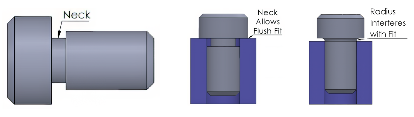
A neck is an important feature found on the outer surface of cylindrical components. It serves a vital purpose by creating a seamless transition between different diameters, helping to prevent any potential interference between connecting parts due to the radius of cutting tools. Figure 10-1 illustrates how a neck can be used to allow proper assembly of components.
Additionally, this neck—often called a relief—is also beneficial at the end of threading operations; it provides the necessary clearance for the threading tool and ensures that mating threads can be fully engaged without any obstruction, as shown in Figure 10-2.

When it comes to dimensioning necks, there are two methods that may be used. A leader line with a note containing the neck width and radial depth information or dimension and extension lines with the measurement values can be used. See Figure 10-3. It’s important to remember that sometimes precise neck sizes may not be critical enough to warrant specific dimensions. However, please keep in mind that if the neck is deeper than necessary, it could create a weak point within the component.

Necks on threaded components may be dimensioned as shown in Figure 10-4, as the diameter needs to be only smaller than the minor diameter of the thread.

10.3 Grooves
While necks refer to a recess on an outside diameter at the intersection of different diameters, a groove is a recess anywhere along an outside or inside diameter. Grooves are typically used for lubrication pathways, seals, and internal or external retaining rings. See Figure 10-5 for an illustration of grooves.

As with a neck, a groove may be dimensioned using a leader note or dimension and extension lines, as shown in Figure 10-6.

Another common outside groove is the V-groove, typically used on pulleys for use with a “V”-shaped belt. A V-groove is commonly dimensioned with the V angle and the depth of the groove. See Figure 10-7.

10.4 Slotted Holes
Slots are features that often serve as a connection with another piece and are often used to provide adjustment. Slotted holes typically have a full radius on each end and may be dimensioned in various ways. Observe the three styles of dimensioning a slotted hole. The dimensions may locate the center point locations and width, center point locations and radius, or the outer dimensional sizes of the slot, as depicted in Figure 10-8.

10.5 T-Slots
T-slots play an important role in machining tables and various fixturing devices, as they enable secure clamping of workpieces with T-bolts. Recognized by their distinctive upside-down “T” shape, these slots offer the flexibility to adjust the placement of clamps according to specific needs. Figure 10-9 shows a T-slot.

10.6 Dovetail Slots
Dovetail slots play a crucial role in machinery that requires precise and reliable movement between components. You can often find them on milling machine tables, cross-slides, lathe cross-slides, and compound rests. When creating T-slots and dovetail slots using a milling machine, two tools will typically be needed: one to remove the material for the width of the top opening and another to shape the undercut features. Dovetail slots are portrayed in Figure 10-10.

10.7 Keyways and Keyseats
A key is an important fastener that helps connect a circular shaft and hub, ensuring they work together smoothly without rotating independently. You will often find these keys in various applications, such as gears, pulleys, hand-wheels, and cutting tools. They can come in different shapes, with square or rectangular options known as keystock being quite common. There’s also the Woodruff key, which has a unique half-circular design, allowing its rounded part to fit securely into the shaft. The choice between a Woodruff key and a flat key depends on the specific application and requirements. Factors such as load capacity, space availability, and installation convenience are considered when selecting the key type.
The area on the shaft that is cut to receive the key is referred to as the keyseat. Keyseats are grooves cut along the shaft length to allow the key to sit in. These are cut with a milling machine using an endmill or special straight-fluted endmill designed for cutting keyways. Woodruff keyseat cutters have an upside-down “T” shape that creates a circular recess in the center of the shaft. Woodruff keys and keyseat cutters are identified by numbers representing their width in 1/32 of an inch and diameter in 1/8 of an inch. As an example, a #806 Woodruff key would have a width of 8/32 or 1/4 and a diameter of 6/8 or 3/4. In another example, a #1008 Woodruff key will have a width of 5/16 and a diameter of 1 inch. See Figure 10-11.

The keyway is the groove along the internal length of the hub for the key to fit into. Keyways can be cut into the holes of the hub using a keyway broach set and press or by using a wire EDM (electrical discharge machining) machine, depending on the equipment available, as shown in Figure 10-12.

Keyways and keyseats may be dimensioned by width and height or depth, or they may be noted with a leader line and local note. The standard dimensions for various key sizes can be referenced in texts such as the Machinery’s Handbook. Figure 10-13 shows a keyway dimensioned from the keyway to the opposite diameter.

A keyseat is often dimensioned by the keyseat width and from the bottom of the keyseat to the opposite diameter, as depicted in Figure 10-14.

10.8 Bosses and Pads
A boss and a pad are essential features in casting, designed to enhance the machining process that follows. A raised area that is circular in shape is referred to as a boss. A pad is a raised area of any other shape (but often oblong). These features are often used for a contact surface with a fastener or another mating part. This surface is often machined to obtain a flatter contact surface. View Figure 10-15 for an illustration of a boss and a pad.

10.9 Thread Terms
A screw thread is a helical ridge wrapping around a cylindrical shape. A helical shape (or helix) is a shape uniformly wrapping around a cylinder. An external thread is on the outside of a cylinder, such as the threads on a bolt, as shown in Figure 10-16. An internal thread is a thread on the cylinder of a hole, such as in a nut or tapped hole, as shown in Figure 10-17. The V-type thread design is the most prevalent type of thread used and plays a significant role in numerous industrial parts, primarily in fastening components together. Other thread shapes like the square thread are frequently applied in applications related to power transmission, such as driving axes in milling machines and lathes. The information in this chapter covers common thread terminology, representation, and specifications.
Major diameter is the largest diameter of the thread, measured across the diameter of the crest on an external thread and the diameter measurement across the root of an internal thread. Before cutting an external thread, the part’s starting diameter will be the major diameter.
Minor diameter is the smallest diameter of the thread, measured across the diameter of the crest on an internal thread and the measurement across the root of an external thread.
Pitch is the distance between a point on one thread and the same point on the next thread. Metric will identify the major diameter followed by the pitch; for example, in M10 x 1.25, the pitch is 1.25 mm. An inch thread will identify the major diameter followed by the number of threads in a distance of one inch; for example, in 1/4-20, there are 20 threads within a 1-inch distance. Divide 1 by the number of threads per inch to obtain the pitch on an inch thread. In the 1/4-20 example, 1 divided by 20 will equal a pitch of .05 inch.
Lead is the amount the thread will advance in one revolution. Most threads will have a single start point; in which case the lead will match the pitch of the thread. To advance a thread more quickly, some threads will have multiple start points, known as multiple lead threads. A double lead thread will have two start points and a lead twice its pitch. An everyday example would be the cap of a plastic bottle, which will often have multiple start points.
Thread angle is the angle formed between the threads. The most common “V”-shaped thread will have an angle of 60°.


Pitch diameter is where the thread groove’s width matches the ridge’s width. It is the critical value for obtaining the proper thread fit. See Figure 10-18.

10.10 Thread Representation
Threads may appear on a drawing in a few different ways. Threads may appear as detailed, schematic, or simplified. See these thread variations in Figure 10-19. While the schematic and simplified techniques were most common before the use of CAD systems, they will still be found on many drawings. The detailed thread representation provides a realistic view of the thread but can be difficult to view on smaller thread diameters. In this case, the schematic or simplified may be used to represent the thread.

10.11 Thread Specifications
The details of the thread will be identified with a leader and note. The information will commonly include the major diameter, threads per inch, pitch for metric, thread series, and thread class. Additional information, such as thread direction and the number of starts on a multiple-start thread, may also be included, as shown in Figure 10-20.

Major diameter is the nominal major diameter size. 1/4 inch and larger diameters will use fractional dimensions, and smaller diameters will use a number designation. The specific range for the major diameter size requirements can be referenced in the Machinery’s Handbook.
Threads per inch is the number of threads within a 1-inch length of the thread.
Thread series refers to unified inch threads that will be in one of four thread series: course, fine, extra fine, and constant pitch.
- Unified course threads (UNC) are generally used, and are most commonly on nuts and bolts.
- Unified fine threads (UNF) will have a shorter pitch, which is useful where limited thread engagement is available, such as in thin material or where the thread is used for a fine adjustment application.
- Unified extra fine (UNEF) is less common than UNC and UNF series and used in applications where very little thread engagement is available.
- Unified constant-pitch (UN) is used in high-pressure applications and large-diameter threads.
Thread class refers to the fit tolerance of inch series threads and falls into three classes: 1A, 2A, or 3A for external threads; and 1B, 2B, or 3B for internal threads. These specific tolerance sizes are referenced in books such as the Machinery’s Handbook.
- 1A and 1B are the loosest-fit thread and used in applications where frequent use is required, and a close tolerance is not required.
- 2A and 2B threads are used for general-purpose applications such as nuts and bolts. They are to be used where a thread classification is not included.
- 3A and 3B will have the tightest tolerance and used for more precise applications.
The details included in a metric series thread note will include metric series designation (M), major diameter, thread pitch, and thread tolerance class. See Figure 10-21.

Metric series major diameter – This is the nominal major diameter size in millimeters. The specific range for the major diameter size requirements can be referenced in the Machinery’s Handbook.
Thread pitch – This is the distance between threads in millimeters.
Thread tolerance class – Metric threads use numbers to indicate the amount of tolerance allowed: the smaller the number, the smaller the tolerance. Lowercase letters are used for external threads, and uppercase letters are used for internal threads. A 6H and 6g are comparable to an inch 2A and 2B and are applied when no tolerance is specified. The Machinery’s Handbook and similar texts reference the specific tolerance sizes.
Additional information for a multiple-start thread, such as double-lead or triple-lead, may be included. Right-hand threads are presumed unless an LH is indicated to represent a left-hand thread.
Learning Activities
Exercise 10.10-1
Exercise 10.10-2
Exercise 10.10-3
Refer to the print below to respond to the missing dimensions in the activity beneath it. 
References:
Barsamian, M.A., & Gizelbach, R. (2022). Machine trades print reading. Goodheart-Willcox.
Schultz, R. L., & Smith, L. L. (2012). Blueprint reading for machine trades (7th ed.). Pearson.
Images:
All images by Mark Lorier and licensed under CC BY-NC 4.0 except where otherwise noted.
