Printable Learning Activities by Chapter
Chapter 1: Drawing v. Prints
Exercise 1
- What two categories can the manufacturing process be condensed into?
- a. Design phase and production phase
- b. Sketching phase and assembly phase
- c. Planning phase and testing phase
- d. Prototype phase and final phase
- What is the purpose of the design phase?
- a. To generate essential documentation for product fabrication
- b. To transport components to a specified location for assembly
- c. To create three-dimensional models of the design
- d. To analyze and simulate the performance of the design
- What is the advantage of using a CAD system in the design process?
- a. Speed and efficiency in creating designs
- b. Easy modification of designs
- c. Accuracy in creating designs
- d. All of the above
- What can a 3D model be used for in the manufacturing process?
- a. Creating detailed 2D drawings
- b. Transferring the design directly to production
- c. Analyzing and simulating the performance of the part or assembly
- d. All of the above
- What is the purpose of detailed drawings in the design process?
- a. To provide comprehensive information necessary to manufacture each part
- b. To outline the shape and size of the part
- c. To convey essential specifications such as material types
- d. All of the above
- What is the origin of the term “blueprint”?
- a. It refers to prints with a blue background and white lines
- b. It originated from the process of sketching designs on tracing paper
- c. It refers to the chemical reaction that turns exposed areas white
- d. All of the above
Chapter 2: Views of an Object
View Identification Quiz
Directions: Circle the letter corresponding to the Front, Top, Right, Left, Back, or Bottom, and circle two of the three basic dimensions of Height, Width, or Depth that may be from that view.

Circle one Circle two
Front View: A B C D E F – Height Width Depth
Top View: A B C D E F – Height Width Depth
Right View: A B C D E F – Height Width Depth
Bottom View: A B C D E F – Height Width Depth
Left View: A B C D E F – Height Width Depth
Back View: A B C D E F – Height Width Depth
Surface Identification Quiz 1
Directions: Enter the letters from the pictorial drawing into the correct balloons on the orthographic views.


Surface Identification Quiz 2
Directions: Enter the letters from the pictorial drawing into the correct balloons on the orthographic views.

Chapter 3: Types of Lines
Line Quiz 1
Directions: Using the images below, identify the line type being used below. NOTE: Some lines will be identified more than once.
 |
Centerline
Chain line Cutting-plane line Dimension line Extension line Hidden line Leader Long break line Phantom line Short break line Section line Symmetry line Viewing-plane line Visible line |
|---|
A. ____________________ B. ____________________ C. ____________________
D. ____________________ E. ____________________ F. ____________________
G. ____________________ H. ____________________ I. ____________________
J. ____________________ K. ____________________ L. ___________________
M. ____________________ N. ____________________ O. ___________________
P. ____________________ Q. ____________________
Line Quiz 2
Directions: Using the drawing, identify the line type being used below. NOTE: Some lines will be identified more than once.
 |
Centerline
Chain line Cutting-plane line Dimension line Extension line Hidden line Leader Long break line Phantom line Short break line Section line Symmetry line Viewing-plane line Visible line |
|---|
A. ____________________ B. ____________________ C. __________________
D. ____________________ E. ____________________ F. __________________
G. ____________________ H. ____________________ I. ___________________
J. ____________________ K. ____________________ L. __________________
M. ____________________ N. ____________________ O. __________________
P. ____________________ Q. ____________________
Line Quiz 3
Directions: Enter the name of the line that best matches the descriptions.
- Represents outside edges and intersections. _____________________________
- May be used in place of repeating features or to show an alternate position. _____________________________
- Line that represents an imaginary cut to provide an alternate view. _____________________________
- Points to a feature to provide information or a dimension ending with an arrowhead. _____________________________
- Indicates where an alternate view is taken from. _____________________________
- Represents the solid material that has been cut through. _____________________________
- Indicates a surface or edge not visible in that view. _____________________________
- Ends with arrowheads reaching the distance of the feature to indicate the size. _____________________________
- Lines used in pairs that indicate a part has been shortened to conserve space on the print. _____________________________
- Shows the positioning of holes and the middle of symmetrical parts. _____________________________
- Extends between the ends of the feature being measured to the dimension of the feature. _____________________________
- Indicates where a portion of the part has been broken away to show interior details more clearly or to show where portions of the part have been removed to conserve space. _____________________________
- Highlights a portion of the part requiring special treatment or attention. _____________________________
Word Bank
Centerline Chain line Cutting-plane line
Dimension line Extension line Hidden line
Leader Long break line Phantom line
Section line Short break line Viewing-plane line
Visible line
Line Quiz 4
Directions: Using the drawing below, identify the line type being used below. NOTE: Some lines may be identified more than once.
 |
Centerline
Chain line Cutting-plane line Dimension line Extension line Hidden line Leader Long break line Phantom line Short break line Section line Symmetry line Viewing-plane line Visible line |
|---|
A. ____________________ B. ____________________ C. __________________
D. ____________________ E. ____________________ F. __________________
G. ____________________ H. ____________________ I. ___________________
J. ____________________ K. ____________________ L. __________________
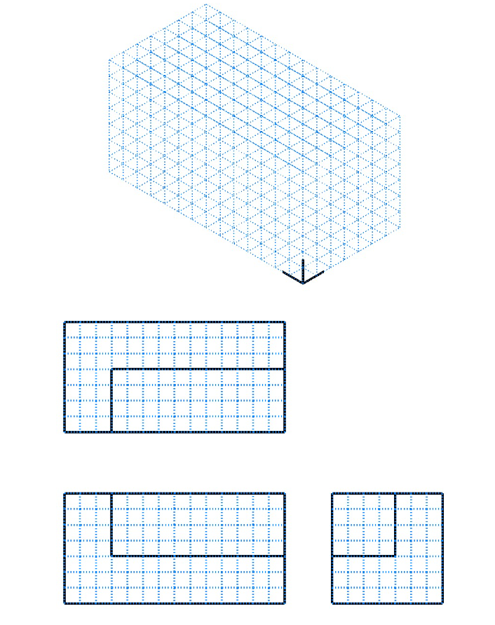
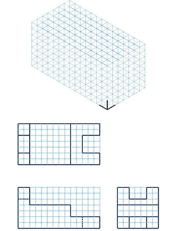
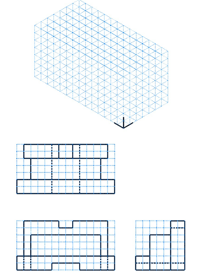
Chapter 4: Objects in Different Views
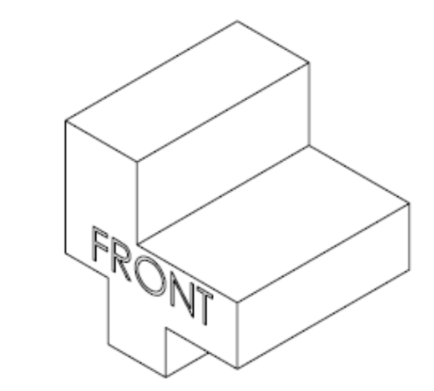
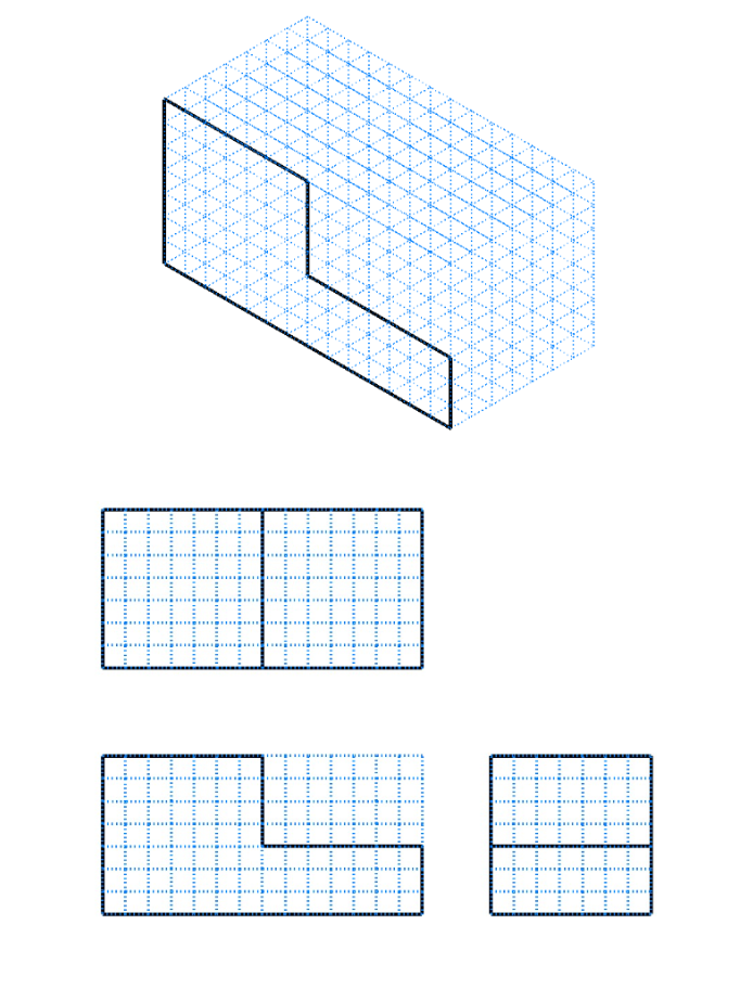
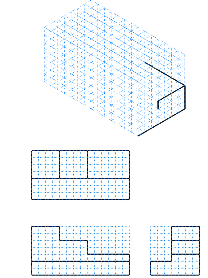
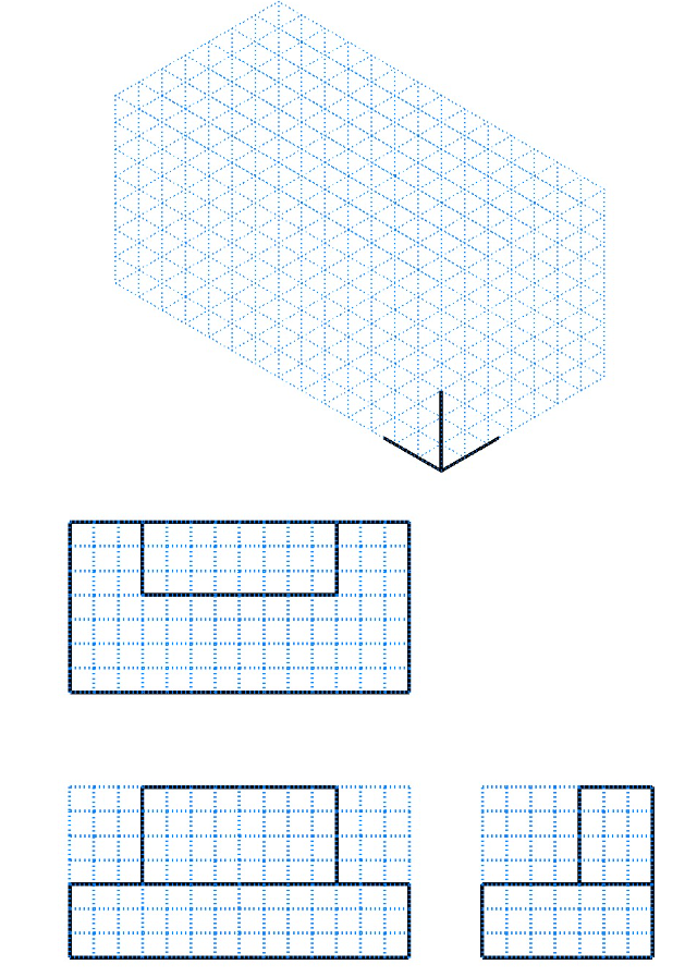
View Identification Exercise 1
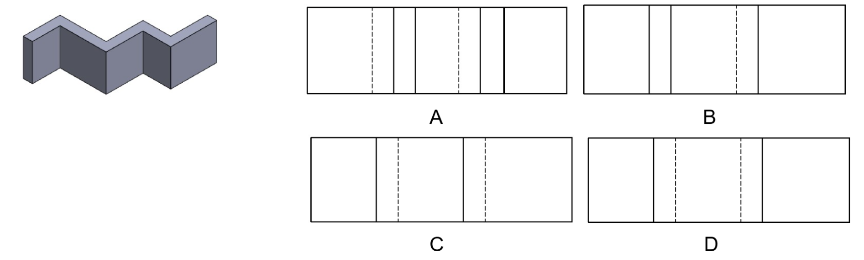
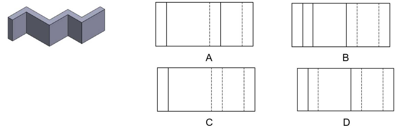
Enter the matching letter of the correct top and right-side views for each isometric view below.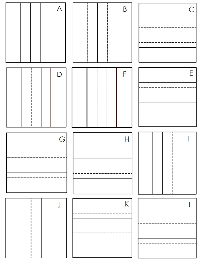
- Top View: _________________
Right View: _______________
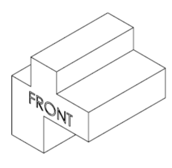
2. Top View: ____________
Right View: ____________
View Identification Exercise 2
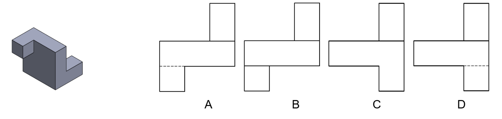
Select the correct orthographic views for each of the isometric views shown.
- Select the letter of the correct Front view
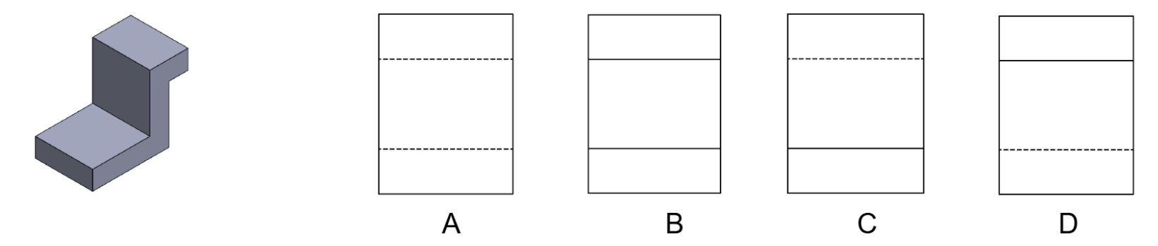
- Select the letter of the correct Front view
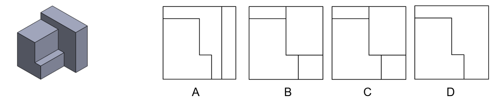
- Select the letter for the correct Right view
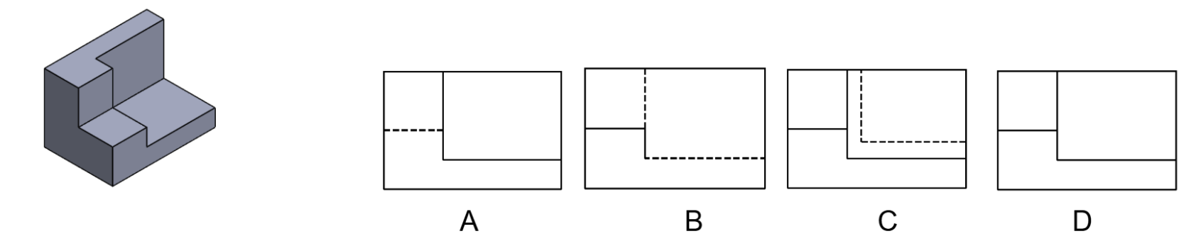
- Select the letter for the correct Right view
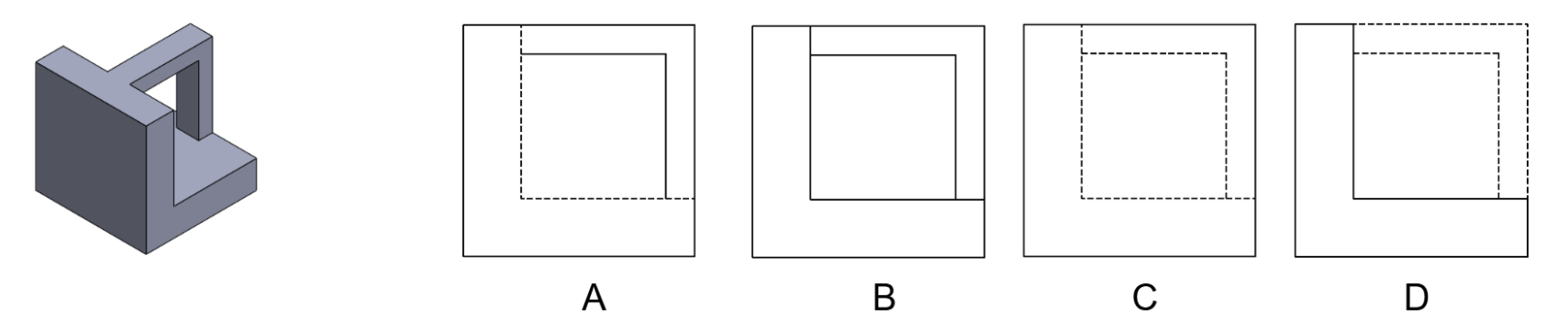
- Select the letter for the correct Front view
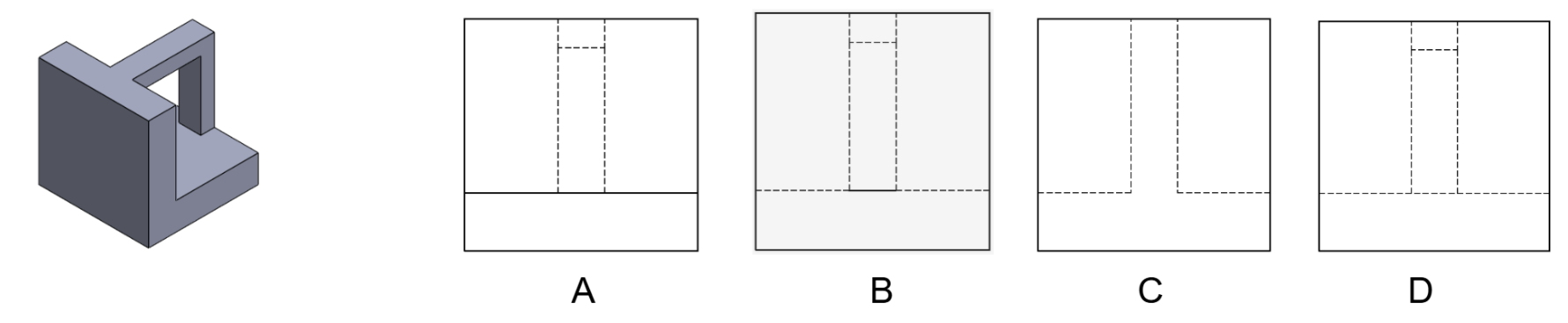
- Select the letter for the correct Right view
- Select the letter for the correct Front view
- Select the letter for the correct Front view
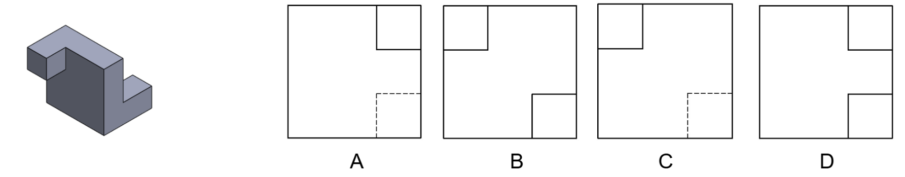
- Select the letter for the correct Right view
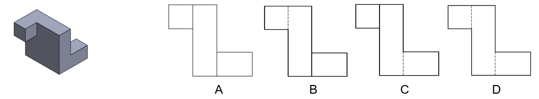
- Select the letter for the correct Top view
Orthographic Sketch 1


Orthographic Sketch 2


Orthographic Sketch 3

Orthographic Sketch 4

Orthographic Sketch 5

Orthographic Sketch 6

Isometric Sketch 1
Isometric Sketch 2
Isometric Sketch 3
Isometric Sketch 4
Isometric Sketch 5
Isometric Sketch 6
Chapter 5: Dimensioning Systems
Exercise 5.2-1
Directions: Calculate the dimensions for letters A through J using the support block below.

A. _________________________ E. _________________________ I. _________________________
B. _________________________ F. _________________________ J. _________________________
C. _________________________ G. _________________________
D. _________________________ H. _________________________
Exercise 5.2-2
Directions: When programming or producing the part, the datum will be the X and Y absolute zero point. Identify the X and Y locations for letters A through L.

A. X __________ Y __________ E. X __________ Y __________ I. X __________ Y __________
B. X __________ Y __________ F. X __________ Y __________ J. X __________ Y __________
C. X __________ Y __________ G. X __________ Y __________ K. X __________ Y __________
D. X __________ Y __________ H. X __________ Y __________ L. X __________ Y __________
Exercise 5.3-1
Directions: Calculate the decimal inch equivalents for the metric dimensions below, and round answers to three decimal places.

A. 9.525) ____________________ F. 63.50) ____________________ K. 15.88) ____________________
B. 12.70) ____________________ G. 76.20) ____________________ L. 10.02) ____________________
C. 15.875) ____________________ H. 6.53) ____________________ M. 17.15) ____________________
D. 19.05) ____________________ I. 9.21) ____________________ N. 11.35) ____________________
E. 50.80) ____________________ J. 10.08) ____________________ O. 12.38) ____________________
Exercise 5.3-2
Directions: Determine the missing fractional dimensions for the adjustment bracket. Refer to the drawing.

A. _________________________ D. _________________________ G. _________________________
B. _________________________ E. _________________________
C. _________________________ F. _________________________
Exercise 5.3-3
Directions: Determine the dimensions for the slide block.

A. _________________________ E. _________________________ I. _________________________
B. _________________________ F. _________________________ J. _________________________
C. _________________________ G. _________________________ K. _________________________
D. _________________________ H. _________________________ L. _________________________
- For the slot labeled “I” on the front view, why does the right hidden line not appear on the top view? _________________________
- Which system of measurement is being used (decimal, fractional, metric)? _________________________
- Which angle of projection is being used? _________________________
Chapter 6: Print Dimensions
Exercise 6.4-1
Directions: Answer the following questions about the exhaust flange print provided.

- Is the flange symmetrical along the vertical or horizontal line? _________________________
- Calculate the overall height of the flange. _________________________
- Calculate the overall width of the flange. _________________________
- What is the thickness of the flange? _________________________
- What is the radius of the large hole? _________________________
- Calculate the distance or wall thickness between the center hole and the top or bottom of the flange. _________________________
- Calculate the wall thickness between one of the small holes and the outside edge. _________________________
- Calculate the distance between the inside edges of the small holes. _________________________
- Without regard to tolerance, calculate the distance between the edge of the large hole and the edge of the small hole. _________________________
- Which dimensioning unit is being used? _________________________
Exercise 6.4-2
Directions: Calculate the following dimensions for the riser plate print provided. Represent all answers in three decimal places.

A. _________________________ E. _________________________ I. _________________________
B. _________________________ F. _________________________
C. _________________________ G. _________________________
D. _________________________ H. _________________________
- What is the overall height of the riser plate (top to bottom)? _____________________
- Without regard to tolerance, what is the largest width of the riser plate (left to right)?_______________________________________________________________
- What prevents the part from being symmetrical along its horizontal centerline? _____________________________________________________________
Exercise 6.4-3
Directions: Use the dimensioned isometric view to complete the dimensions on the orthographic view.

- Height: _________________________ 4. A) _________________________ 7. D) _________________________
- Width: __________________________ 5. B) _________________________ 8. E) _________________________
- Depth: _________________________ 6. C) _________________________ 9. F) _________________________
Exercise 6.4-4
Directions: Find the dimensions for the letters below using the multiple views.

- A) _________________________ 6. F) _________________________ 11. K) _________________________
- B) _________________________ 7. G) _________________________ 12. L) _________________________
- C) _________________________ 8. H) _________________________ 13. M) _________________________
- D) _________________________ 9. I) __________________________ 14. N) _________________________
- E) _________________________ 10. J) __________________________
Exercise 6.5-1
Directions: Answer the questions referencing the prick punch print provided.

- What is the angle included in the punch tip? _________________________
- What is the length of the knurled portion, NOT including the chamfers? _________________________
- Which type of line is being used to identify the portion to be flame-hardened? _________________________
- How much change in diameter occurs in the tapered portion? _________________________
- What is the diameter A dimension? _________________________
- What is the length of dimension B? _________________________
- What is the length of dimension C? _________________________
- How many .03 x 45° chamfers are on the part? _________________________
Exercise 6.5-2
Directions: Find the dimensions for the letters below using the multiple views.

- 1. A) _________________________ 6. F) _________________________ 11. K) _________________________
- 2. B) _________________________ 7. G) _________________________
- 3. C) _________________________ 8. H) _________________________
- 4. D) _________________________ 9. I) _________________________
- 5. E) _________________________ 10. J) _________________________
Exercise 6.6-1
Directions: Answer the following questions about the pump seal print below.

- Is the seal symmetrical along the vertical or horizontal centerline? _________________________
- How thick is the seal? _________________________
- How many .25 radii are on the seal? _________________________
- Are the three bolt circles concentric? _________________________
- How many holes are on the part? _________________________
- What is the angular spacing between the ⌀.28 holes? _________________________
- What is the angular spacing between the ⌀.53 holes? _________________________
- What is the wall thickness between the ⌀.53 hole and the nearest outside edge? _________________________
Enter the dimensions for the letters:
9. A) ___________
10. B) ___________
11. C) ___________
12. D) ___________
Exercise 6.6-2
Directions: Calculate the angular dimensions for the letters. Recall the angle between equally spaced bolt circles is 360° divided by the number of holes. A bolt-hole location will be located on or dimensioned from a vertical or horizontal line.

A. _________________________ E. _________________________ I. _________________________
B. _________________________ F. _________________________ J. _________________________
C. _________________________ G. _________________________ K. _________________________
D. _________________________ H. _________________________ L. _________________________
Chapter 7: Title Blocks
Exercise 7.4-1
Directions: Refer to the shaft project to answer the following questions.

- What is the drawing number for the print? _________________________
- By whom was the drawing checked? _________________________
- What is the name of the company responsible for the drawing? _________________________
- What is the scale of the print? _________________________
- Describe in words what the scale of this drawing means. _________________________
- What material is required for this part? _________________________
- What style of dimensioning is being used for the project? _________________________
- What is the tolerance for two-place decimal dimensions? _________________________
- What is the size tolerance of the ⌀2.000 dimension? _________________________
- What is the size tolerance of the ⌀1.875 dimension? _________________________
- How many pieces are required? _________________________
- What is the size of the stock from which the project is made? _________________________
Exercise 7.4-2
Directions: Refer to the pump cover below to answer Questions 1 through 5 and identify the dimensions for letters A through L.

- What is the drawing number for the print? _________________________
- What is the sheet size letter of the drawing? _________________________
- What material is required for the pump cover? _________________________
- What revision was made to the pump cover? _________________________
- What is the overall length along the centerline? _________________________
A. _________________________ E. _________________________ I. _________________________
B. _________________________ F. _________________________ J. _________________________
C. _________________________ G. _________________________ K. _________________________
D. _________________________ H. _________________________ L. _________________________
Exercise 7.4-3
Directions: Answer the following questions for the front limit switch bracket drawing.

- How many holes are on the bracket? _________________________
- What system of measurement is used? _________________________
- What size is the largest hole? _________________________
- What size is the smallest hole? _________________________
- How long is the bracket? _________________________
- What is the material thickness? _________________________
- What is the material thickness in thousandths of an inch? _________________________
- How many revisions were made to the bracket? _________________________
- What was revision C? _________________________
- In which zone is revision C? _________________________
- What type of break line is used? _________________________
- What revision level is the drawing? _________________________
Calculate the following dimensions along with their accumulated tolerances.
A. ________________________________________
B. ________________________________________
C. ________________________________________
D. ________________________________________
E. MAX ________________________________________ MIN ________________________________________
F. MAX ________________________________________ MIN ________________________________________
Chapter 8: Tolerance on Dimensions
Exercise 8.9-1
Directions: Calculate the distance and tolerance accumulations for the distances between the letters below.

A to B = ________ ± ________
A to D = _______ ± ________
A to H = _______ ± ________
B to C = _______ ± ________
D to H = _______ ± ________
G to H = _______ ± ________
Exercise 8.9-2
Directions: Calculate the distance and tolerance accumulations for the distances between the letters below.

A to B = ________ ± ________
A to D = _______ ± ________
A to H = _______ ± ________
B to C = _______ ± ________
D to H = _______ ± ________
G to H = _______ ± ________
Exercise 8.9-3
Directions: Find the dimensions for the letters and the accumulated tolerances.

- A) _________
- How much tolerance accumulates for dimension A? ±________
- B) _________
- How much tolerance accumulates for dimension B? ±________
- C) _________
- How much tolerance accumulates for dimension C? ±________
- D) _________
- How much tolerance accumulates for dimension D? ±________
- E) _________
- How much tolerance accumulates for dimension E? ±________
- F) _________
- How much tolerance accumulates for dimension F? ±________
- G) _________°
- H) _________°
Exercise 8.9-4
Directions: Answer Questions 1 through 6 for the drawing.

- How much tolerance applies to the thickness of the part? _________________________
- Is the thickness tolerance limit, bilateral or unilateral tolerancing? _________________________
- What is the MMC of the 1.1809 diameter? _________________________
- What is the LMC of the 2.047 diameter? _________________________
- Are the 1.1809 and 2.047 diameters limit, bilateral or unilateral tolerancing? _________________________
- What is the maximum overall length of the part, including tolerances? _________________________
Use all tolerance values to find the maximum and minimum values for the matching letters.
A. MAX ________________________________________ MIN ________________________________________
B. MAX ________________________________________ MIN ________________________________________
C. MAX ________________________________________ MIN ________________________________________
D. MAX ________________________________________ MIN ________________________________________
E. MAX ________________________________________ MIN ________________________________________
F. MAX ________________________________________ MIN ________________________________________
G. MAX ________________________________________ MIN ________________________________________
H. MAX ________________________________________ MIN ________________________________________
Exercise 8.9-5
Directions: Answer Questions 1 through 10 for the drawing.

- Does the drawing contain any single-limit dimensions? __________________________
- What type of tolerance is applied to the 5 holes? _______________________________
- What type of tolerance is applied to the .750 dimensions? ________________________
- What type of tolerance is applied to the hole spacing on the front view? _____________
- What type of tolerance is applied to the 2.0000 dimension? _______________________
- Express the hole size dimension as an equal bilateral dimension. __________________
- Calculate the minimum dimension between the centers of the top and bottom holes. _____________________
- Calculate the maximum dimension between the centers of the top and bottom holes. _____________________
- Calculate the minimum distance between the top of the block and the center of the top row of holes. ____________________
- Calculate the maximum distance between the top of the block and the center of the top row of holes. ____________________
Chapter 9: Print Symbols and Notes
Exercise 9.6-1
Directions: Match the correct term to the identifying number.

- ________________ GD&T Symbol
- ________________ Tolerance
- ________________ Modifier
- ________________ Datum
- ________________ Datum Reference
- ________________ Basic Dimension
Exercise 9.6-2
Directions: Answer the questions below referencing this slide block print.

- How many geometric tolerances are identified? ________________
- How many separate datums are identified? ________________
- What surface finish is required? ________________
- What is the surface finish value in decimal form? ________________
- Is the surface finish note a general or local note? ________________
- What does FAO abbreviate? ________________
- What is the geometric characteristic symbol on the datum A surface? ________________
- What is the geometric characteristic symbol on the datum B surface? ________________
- What is the value of the basic dimension? ________________
- What is the scale of the drawing? ________________
Calculate the following dimensions along with their accumulated tolerances.
A. MAX____________MIN_____________
B. MAX____________MIN_____________
C. MAX____________MIN_____________
D. MAX____________MIN_____________
E. MAX____________MIN____________
Exercise 9.6-3
Directions: Answer the following questions for the soft jaw drawing.

- How many datum features are identified? ________________
- Is machining required to obtain the surface finish? ________________
- What is the MMC of the ⌀.53 holes? ________________
- How many feature control frames are being used? ________________
- Which dimension is in limit style? ________________
- Which dimension(s) is unilateral? ________________
- What is the surface finish value in decimal form? ________________
- What size fasteners are intended for the .53 diameter holes? ________________
- How many parts are required? ________________
- Are the GD&T symbols tolerances of size, location, orientation, or form? ________________
- What is the LMC of the .551 slot? ________________
Calculate the following dimensions, along with their accumulated tolerances.
A. ____________
B. ____________
C. ____________
D. ____________
E. MAX____________MIN____________
F. MAX____________MIN_____________
G. MAX____________MIN_____________
H. MAX____________MIN_____________
I. MAX____________MIN_____________
Exercise 9.6-4
Directions: Answer the questions below referencing this slide block print.

- What value is identified as a basic dimension? ________________
- How many geometric tolerances are identified? ________________
- How many separate datums are identified? ________________
- How many pieces are required? ________________
- Is the number of pieces required note a general or local note? ________________
- How many countersink dimensions are identified? ________________
- What surface finish values are identified? ________________
- What are the surface finish values in decimal form? ________________
- What is the geometric characteristic symbol on the datum A surface? ________________
- At what height is the positional tolerance to be measured? ________________
- If two pieces were to fit together at the .30 diameters, what is the minimum amount of clearance? ________________
- What is the maximum amount of clearance between the .300 and .301 diameters? ________________
- What type of tolerance is the 0.181/0.180 value? ________________
- What type of tolerance does the ⌀0.300 value have? ________________
- What is the depth of the tapped hole? ________________
- What is the value of dimension “A”? ________________
- What is the scale of the drawing?________________________________
Chapter 10: Machining Details
Exercise 10.10-1
Directions: Answer the questions below referencing the cross slide print.

- Not including tolerance, what is the depth or the T-slot? ________________
- Not including tolerance, what is the width across the top of the T-slot? ________________
- What is the minimum width across the top of the T-slot? ________________
- What is the maximum depth of the dovetail slot? ________________
- What is the minimum width across the narrow end of the dovetail slot? ________________
- What is the maximum width of the slotted hole? ________________
- What is the maximum overall length of the slotted hole? ________________
- How many threads per inch on the 4 threaded holes? ________________
- What is the pitch of the 4 threaded holes? (round to three decimal places) ________________
- What does the abbreviation UNC stand for? ________________
- What class of fit is designated for the 4 threaded holes? ________________
- What is the nominal major diameter of the 3 threaded holes in mm? ________________
- What is the nominal major diameter of the 3 threaded holes in decimal inches? (round to two decimal places) ________________
- What is the pitch of the 4 threaded holes? ________________
- Which dimensioning style is used for the spacing of the 3 threaded holes on the front view, datum, chain, or broken-chain? ________________
Exercise 10.10-2
Directions: Answer the questions below referencing the container print.

- What is the minimum depth of the ⌀ .88 hole? ________________
- What is the maximum diameter of the largest outside diameter of the container? ________________
- What is the width of the neck, not including tolerance? ________________
- What is the minimum diameter of the neck? ________________
- What is the maximum diameter of the neck? ________________
- What is the major diameter of the thread? ________________
- How many of the threads will there be in a length of ½ inch? ________________
- To the nearest three-place decimal, what is the pitch of the thread? ________________
- Is the thread a single, double, or triple start thread? ________________
- To the nearest three-place decimal, what is the lead of the thread?________________
Exercise 10.10-3
Directions: Answer the questions below referencing the seal pin print and illustration.


- What is the MMC of the ⌀2.00 dimension? ________________
- What is the value of dimension A, not including tolerance? ________________
- What is the value of dimension B, not including tolerance? ________________
- What is the minimum value of dimension B? ________________
- What is the value of dimension C, not including tolerance? ________________
- What is the diameter of the Woodruff keyseat? ________________
- What is the width of the Woodruff keyseat? ________________
- What is the angle of dimension D? ________________
- What is the diameter of dimension E, not including tolerance? ________________
- Using the linear length dimensions, what is the value of dimension F, not including tolerance? ________________
- What is the tolerance accumulation of dimension F? ________________
- What is the value of dimension G, not including tolerance? ________________
- What is the diameter of dimension H? ________________
- What is the maximum diameter of H? ________________
- What is the value of dimension I, not including tolerance? ________________
- What is the value of dimension J, not including tolerance? ________________
- What is the maximum value of J? ________________
Chapter 11 – Section Views
Exercise 11.8-1
Directions: Answer the following questions for the spindle hub drawing.

- What do the parallel lines on the bottom of the top view indicate? __________________
- What type of sectional view is used? _________________________________________
- Is the drawing half the size or twice the size of the actual part? ___________________
- Do the section lines match the style of the material used? _________________
- Which dimension is in limit style? ___________________________________________
- Which dimension is unilateral? _____________________________________________
- Which dimension is equal bilateral? _________________________________________
- Which dimension is an example of a single limit? _______________________________
Calculate the following dimensions along with their accumulated tolerances.
A = ________ ± ________
B = _______ ± ________
C = _______ ± ________
D = _______ ± ________
E = _______ ± ________
F = _______ ± ________
G = _______ ± ________
H = _______ ± ________
I = _______ ± ________
J. MAX____________MIN____________
Exercise 11.8-2
Directions: Using the adjustable arm support print, answer Questions 1 through 7 and find the dimensions for letters A through I.

- What type of sectional view is used? ________________________________________
- What is the sheet size letter of the drawing? ___________________________________
- Which view is replaced with the sectional view? ________________________________
- What is the counterbore depth? _____________________________________________
- What is the LMC of the .5000 hole? _________________________________________
- What is the overall height of the support? _____________________________________
- Does the surface finish symbol indicate that material removal is required? ___________
A = ________
B = ________
C = ________
D = ________
E = ________
F = ________
G = ________
H = ________
I. MAX____________MIN____________
Chapter 12 – Auxiliary Views
Exercise 12.3-1
Directions: Enter the letters from the isometric drawing below into the top of the correct balloons and indicate whether it is a true shape view with a “T,” an inclined surface with an “I,” or a curved surface with a “C” in the bottom of the balloon on the orthographic view.

Exercise 12.3-2
Directions: Enter the letters from the isometric drawing below into the top of the correct balloons and indicate whether it is a true shape view with a “T,” an inclined surface with an “I,” or a curved surface with a “C” in the bottom of the balloon on the orthographic view.

Exercise 12.4-1
Directions: Answer the following questions for the lathe part drawing.

- What type of view replaces the primary views on the right and left? ________________
- What is the nominal major diameter of the internal thread? ________________
- What is the scale of the drawing? ________________
- Not including tolerance, what is the depth of the straight keyway from the outside diameter? ________________
- Which type of view is used to dimension the internal groove? ________________
- Which dimension is a reference dimension? ________________
- What is the pitch of the metric thread? ________________
- What are the threads per inch of the ⅝ thread? ________________
- Rounded to three decimal places, what is the pitch of the ⅝ thread? ________________
- Rounded to four decimal places, what is the pitch of the internal thread? ________________
- What is the fit classification of the internal thread? ________________
- What is the largest size diameter allowed for the small neck diameter? ________________
- Including tolerance, what is the maximum diameter of the internal groove? ________________
- Not including tolerance, what is the length of dimension A? ________________
- What is the maximum overall length of the part? ________________
Exercise 12.4-2
Directions: Answer the following questions for the punch carrier slide drawing.

- How many threads per inch is the largest threaded hole? ________________
- What is the pitch of the ¼-20 threaded hole? (two decimal places) ________________
- What is the scale of the auxiliary view? ________________
- Which primary view is the auxiliary view projected from? ________________
- Which dimension is in limit style?
- What is the MMC of the .748 dimension? ________________
- Which view shows the dimensional locations of the ¼-20 holes? ________________
- What is the maximum depth of the .220 dimension? ________________
- What is the smoothest surface finish required on the slide? ________________
- Not including hidden surfaces, how many of the views contain a foreshortened surface? ________________
Calculate the following dimensions along with their accumulated tolerances.
A. ___________ ± ___________
B. ___________ ± ___________
C. ___________ ± ___________
D. ___________ ± ___________
E. ___________ ± ___________
F. ___________ ± ___________
G. ___________ ± ___________
H. MAX ___________ MIN ___________
I. MAX ___________ MIN ___________
Exercise 12.6-1
Directions: Answer the following questions for the seal pin drawing.

- What type of material is used for the seal pin? ________________
- What type of view are details B and C? ________________
- What is the scale of detail C? ________________
- What surface or feature is the auxiliary view projected from? ________________
- Is the ⌀.625 tolerance a unilateral, equal bilateral, or limit style? ________________
A. ___________
B. ___________ ± ___________
C. ___________ ± ___________
D. ___________ ± ___________
E. ___________ ± ___________
F. ___________ ± ___________
G. ___________ ± ___________
Chapter 13 – Assembly Prints
Exercise 13.5-1
Directions: Refer to the grinding vise drawing to answer the following questions.

- What sheet size is used for this drawing? ________________
- How many parts are used in the vise assembly? ________________
- What is the description of item 5? ________________
- What type of assembly view is used to identify the parts? ________________
- How are items 4 and 5 assembled? ________________
- What is the scale of the assembly drawing? ________________
- What is the part number of item number 6? ________________
- What is the revision level of the drawing?________________
Exercise 13.5-2
Directions: Refer to the punch carrier slide 1 drawing to answer the following questions.

- What are the dimensions of the sheet used for this drawing? ________________
- How many total parts are used in the assembly? ________________
- What is the description of item 9? ________________
- Does the assembly use a multi-view or pictorial view? ________________
- How many threaded fasteners are used? ________________
- What is the scale of the assembly drawing? ________________
- What is the part number of item number 10? ________________
- Is the assembly half the size or twice the size on the drawing? ________________
Exercise 13.5-3
Directions: Refer to the table stop drawing to answer the following questions.

- What sheet size is used for this drawing? ________________
- How many items are used in the table stop assembly? ________________
- What is the description of item 3? ________________
- What type of section view is used? ________________
- What is the scale of the assembly drawing? ________________
- What are the dimensions of the sheet used for this drawing? ________________
- What is the description of item 9? ________________
- How many threaded fasteners are used? ________________
Chapter 14 – Print Specifications
Exercise 14.5-1
Directions: Layout and scribe this workpiece according to the print.

Exercise 14.5-2
Directions: Scribe the circles for the 1.500, 2.754/2.752, and 3.75-diameter circles. Consult the Machinery’s Handbook for the “Chord Length for Given Number of Divisions” for the diameter of the bolt circle and the number of holes required to find the distance to set the divider to lay out the bolt hole locations, as shown in Figure 14-10.


Exercise 14.5-3
Directions: Layout and scribe this workpiece according to the print.

Exercise 14.5-4
Directions: Layout and scribe this workpiece according to the print.

Images:
All images by Mark Lorier and licensed under CC BY-NC 4.0 except where otherwise noted.
