3. Types of Lines Found on Prints
3.1 Introduction
Learning Objectives
- Identify various lines used on prints
- Describe the purposes of the various types of lines used on prints
- Locate lines used on prints
Terms
- Alphabet of lines
- Visible line
- Hidden line
- Centerline
- Cutting-plane line
- Viewing-plane line
- Section line
- Dimension line
- Extension line
- Leader line
- Symmetry line
- Short break line
- Long break line
- Phantom line
- Chain line
- Precedence of lines
Each line on a print serves a unique purpose, conveying critical information with precision. The ASME, an independent organization, sets the standards that guide these engineered drawings. One of their guidelines is the alphabet of lines, an organized system in which every distinct line has its specific role.
It’s truly essential to grasp the alphabet of lines if you want to accurately visualize and interpret a drawing. Lines come with different traits—some are solid or continuous without any breaks, while others appear as dashes with spaces in between. The width of these lines can also vary, being either thin or thick based on their purpose. Understanding these nuances is key to making sense of any detailed drawing.
3.2 Alphabet of Lines
Visible Line
Visible lines, often called object lines, are essential for highlighting every edge and intersection of an object in the view. These thick, continuous lines are designed to stand out clearly on any print. See Figure 3-1 for a representation of visible lines.

Hidden Line
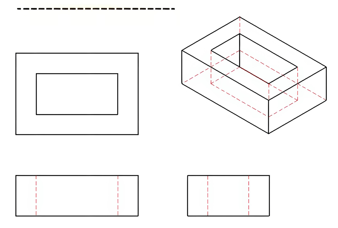
Hidden lines represent the edges or surfaces not visible from the view. These lines have a series of evenly spaced thin dashes, as shown in Figure 3-2.
Centerline
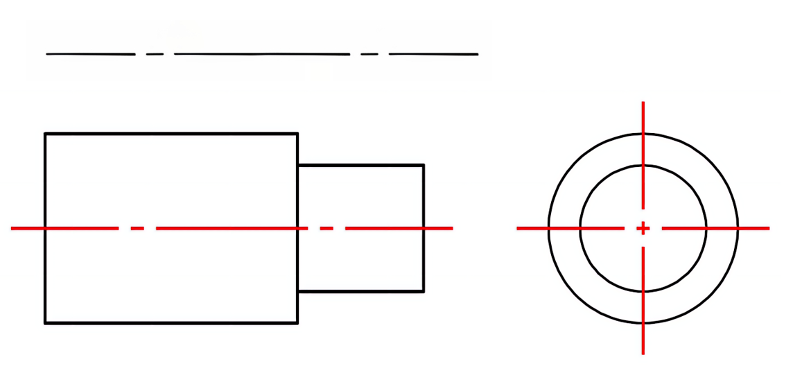
Centerlines are essential in identifying the exact center point of a hole or the axis of a part, and they can also mark the center of an arc or path of motion. As shown in Figure 3-3, these lines are drawn thin and consist of alternating long and short dashes.
Cutting-plane Line
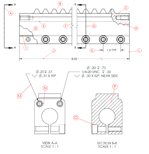
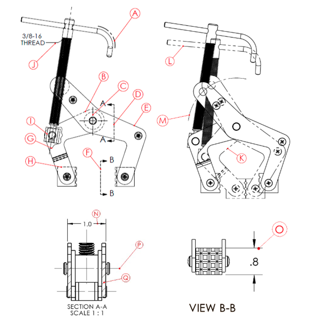
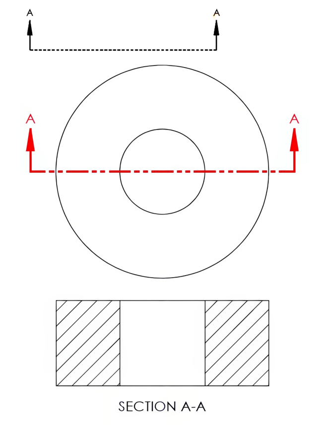
Cutting-plane lines will be drawn on the part to visually represent a “cut” through the material, known as a section view. The style may vary according to the specific standards used by the drafter. Cutting-plane lines are drawn thick, with arrows indicating the direction in which the “cut” section is being viewed. The letters near the arrows are in place to be correctly matched with the corresponding section view. See Figure 3-4 for an example of cutting-plane lines.
Viewing-plane Line
The cutting-plane line and the viewing-plane line are essentially the same; what sets them apart is where they are positioned on the drawing. Unlike the cutting-plane line, which slices through the part, the viewing-plane line is placed near the part to offer a separate view of the object from a specific viewing direction, as depicted in Figure 3-5. When more than one cutting-plane or viewing-plane line is used on a drawing, the letters will be used to correspond with the correct view.
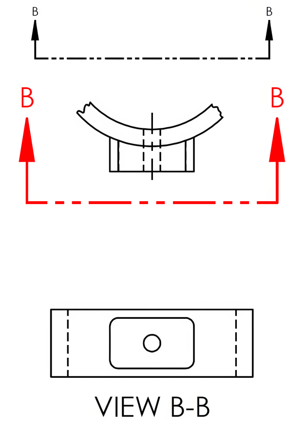
Both cutting-plane and viewing-plane lines may use different line styles than shown above. Figure 3-6 displays an alternative version of the ANSI (American National Standards Institute) style on the left and the ISO (International Organizations for Standardization) style on the right.

Section Lines
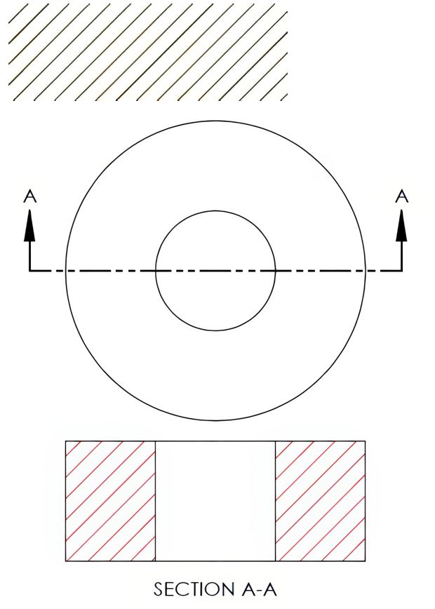
A section view offers a glimpse into the inner workings of a part by showing you what’s inside from one of the primary perspectives. The section lines indicate where the material has been “cut” through, unveiling these interior details; see Figure 3-7. While the diagonal pattern is the most frequently used style for these lines, there are many other styles available that can reflect different types of materials being sectioned. These alternative patterns can be substituted for the more commonly used diagonal style to better represent specific materials.
Dimension Line
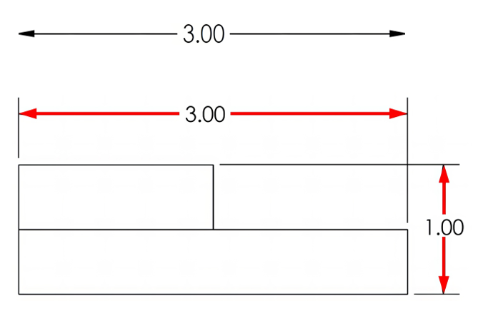
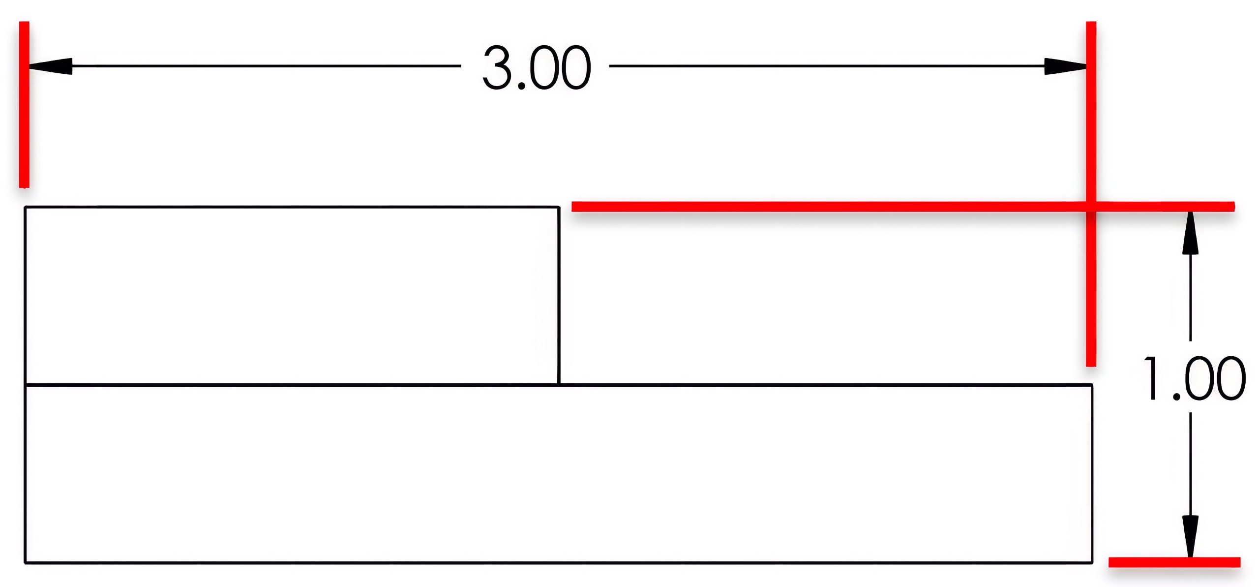
The dimension line spans the distance of the feature measurement and contains the numerical value, called a dimension. These lines will typically end with arrowheads, as shown in Figure 3-8.
Extension Line
The extension lines will reach out from the ends of the dimension lines and extend to the exact point of measurement on the feature. However, they’ll stop just short of actually touching the part or feature, as illustrated in Figure 3-9.
Leader Line
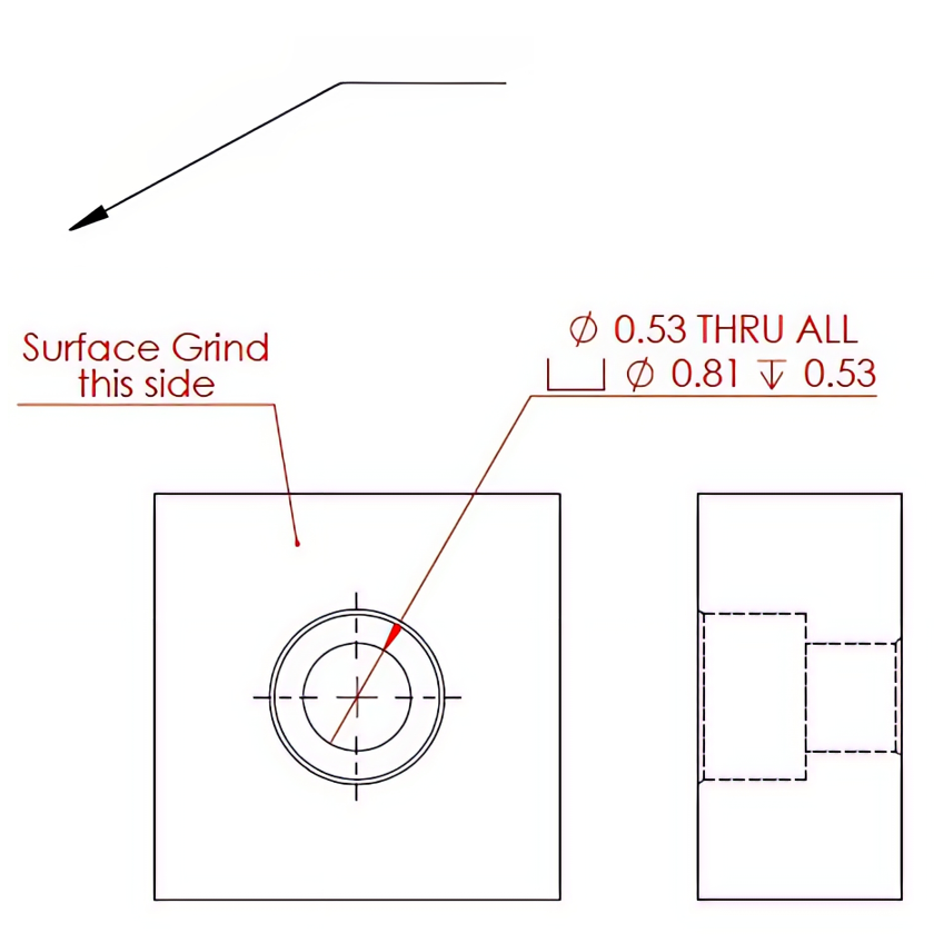
The leader line is a thin slanted line, generally with an arrowhead pointing to a feature to provide information. Information associated with a leader line may include dimensions, notes, item or part numbers, or specific instructions for that feature. The leader may also end with a dot in place of the arrowhead. See Figure 3-10.
Symmetry Line
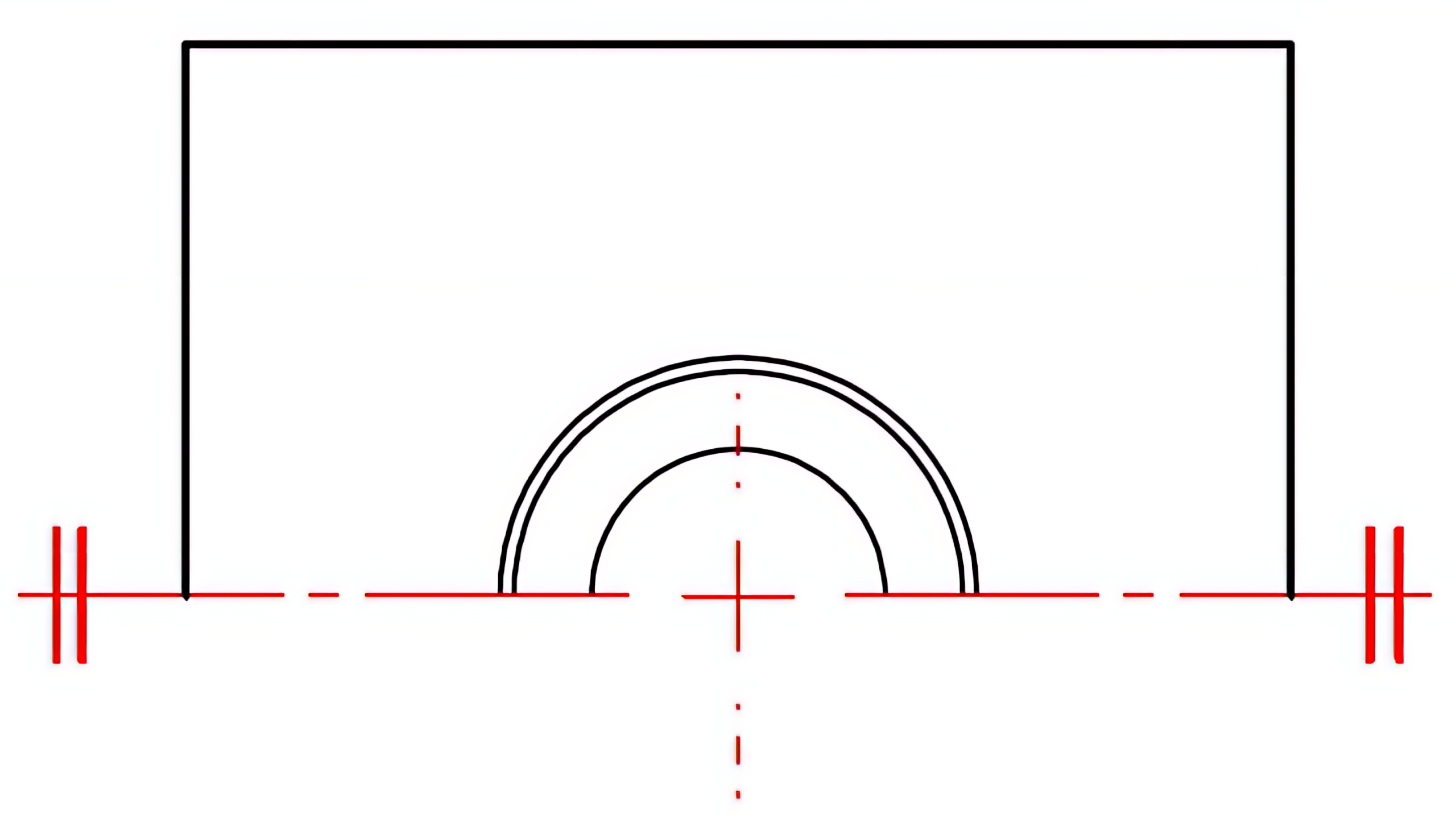
A symmetry line will be used where only one half of a symmetrical part is drawn. This may be used on a part to save space on the drawing. A symmetry line is a centerline accompanied by two thicker parallel lines positioned at each end, perpendicular to the main line. Figure 3-11 shows an example of a symmetry line.
Short Break Line
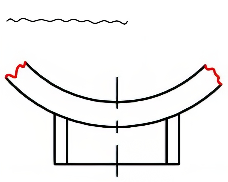
A short break line shows where a part has been broken away to conserve space when the full part does not need to be shown (see Figure 3-12). Short break lines will also be used in broken-out section views, removing material to expose internal part features, as show in Figure 3-13. These lines are drawn in a jagged freehand pattern.

Long Break Line
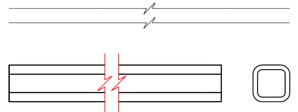
A long break line will be used in pairs to conserve space by removing the central portion of a longer uniform part, allowing a larger drawing scale to be used. These lines are thin and straight with a zigzag shape, used in pairs, and parallel to each other. See Figure 3-14 for an illustration of a long break line. A long break line on a cylindrical part may use an “S”-shaped break line to identify it as cylindrical, as shown Figure 3-15.

Phantom Line
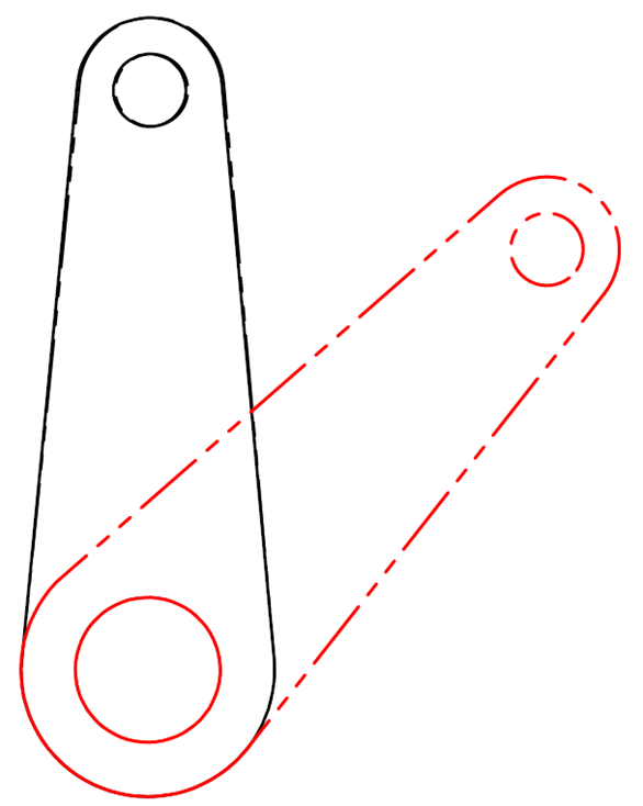
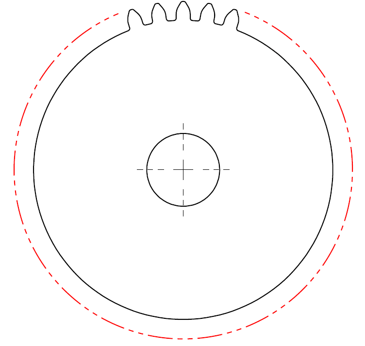
A phantom line is a thin line with a long line followed by two short dashes. A phantom line represents the outline of a part’s alternate position or a mating part/datum plane. This line could also be used to replace repeated details such as threads or gear teeth; this application was more commonly used before CAD systems when prints were hand drawn. See Figure 3-16.
Chain Line
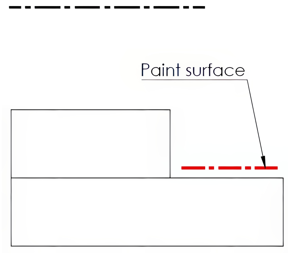
A chain line is characterized by a series of alternating long and short lines, drawn thicker to differentiate from centerlines. This type of line highlights areas on a surface that require special attention or treatment. Additionally, chain lines can mark the projected tolerance zone in geometric dimensioning and tolerancing practices. See Figure 3-17 below for an example of a chain line.
3.3 Precedence of Lines
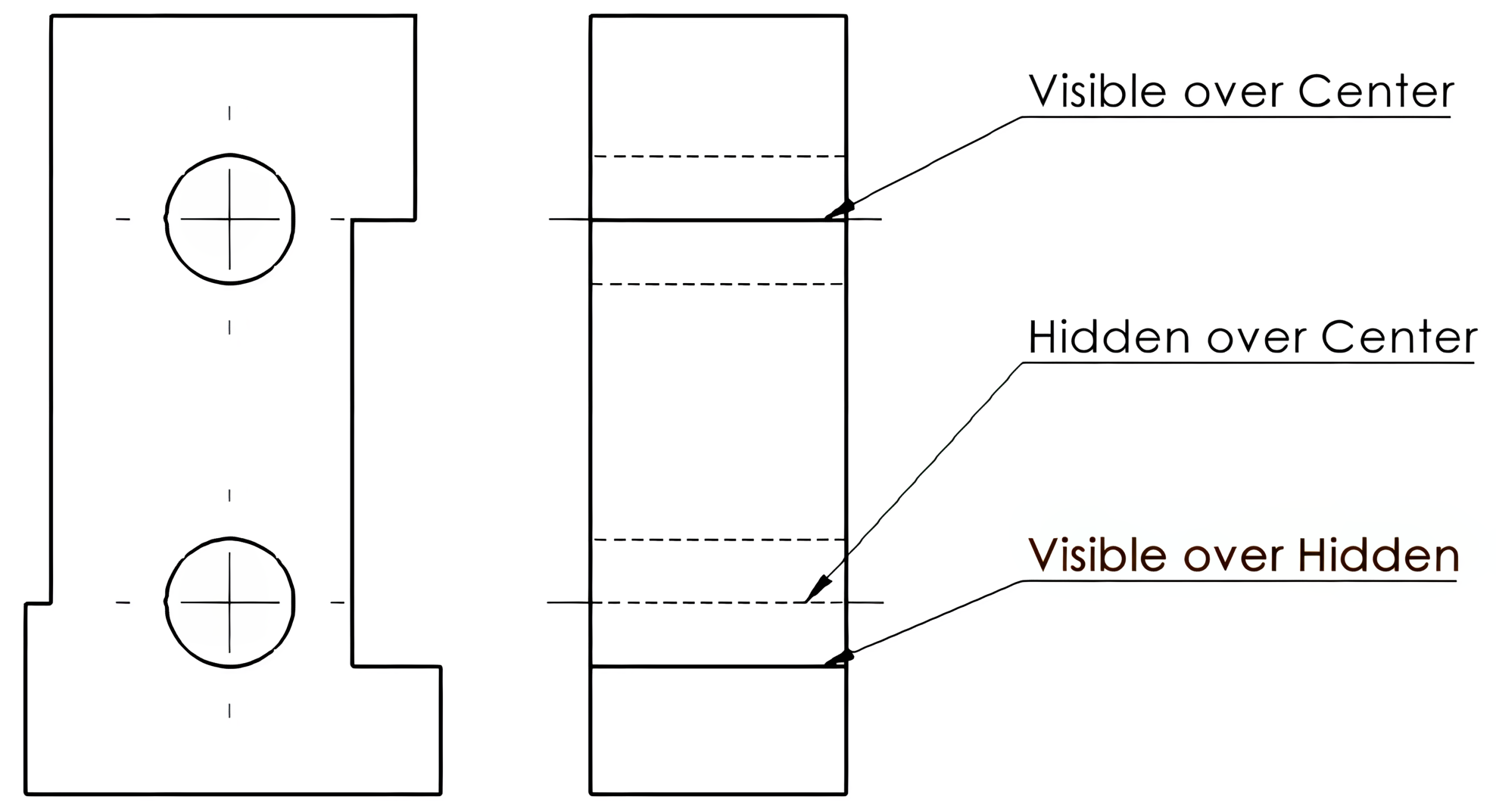
In numerous illustrations, it is common for the lines of a component to coincide in a particular drawing view. The guidelines that govern these situations are referred to as the precedence of lines, which dictate which line remains visible. Visible lines take priority over hidden and centerlines, while hidden lines supersede centerlines in visibility. See Figure 3-18 below.
Learning Activities
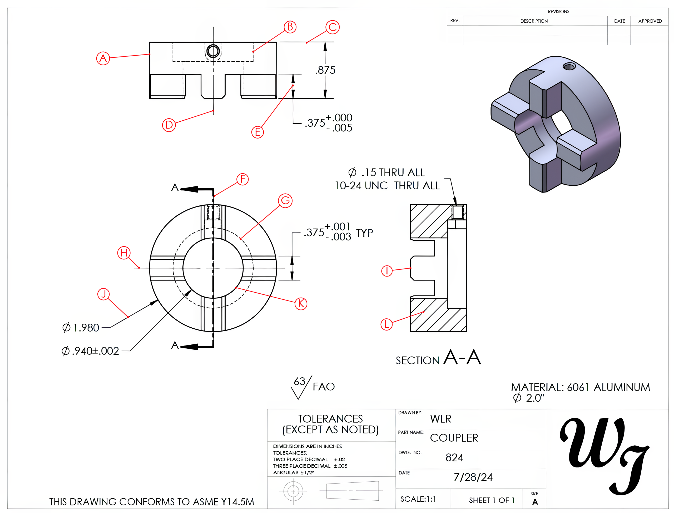
Line Quiz 3
Line Quiz 3
Line Quiz 4
References:
CAERT, Inc. (n.d.). Alphabet of lines [PDF]. https://acrobat.adobe.com/link/review?uri=urn%3Aaaid%3Ascds%3AUS%3A62dfefd9-af0c-3968-9543-9e5062ac8e3a
Schultz, R. R., & Smith, L. (2011). Unit 1: Dictionary of terms. Standard abbreviations: Alphabet of lines. In Blueprint reading for machine trades (7th ed.). Pearson.
Images:
All images by Mark Lorier and licensed under CC BY-NC 4.0 except where otherwise noted.

